
Suspended Cable Transportation Vehicle and System

Inactive Publication Date: 2017-04-20
LOUWSMA KEVIN
View PDF0 Cites 2 Cited by
  • Summary
  • Abstract
  • Description
  • Claims
  • Application Information

AI Technical Summary

Benefits of technology

This patent describes a vehicle that can travel along a cable, like a train along a track. It includes a fuselage, trolley assembly, translation system, seat, counterweight system, and at least one wing. The vehicle has a balance of weight to allow it to easily rotate around the cable while traveling along the line. The rider can also induce roll by activating ailerons or by rotating one of the wings. The translation system has a rotary joint to allow for the roll of the vehicle. Overall, this patent describes a vehicle that is designed to easily travel along a cable and rotate in different directions.

Problems solved by technology

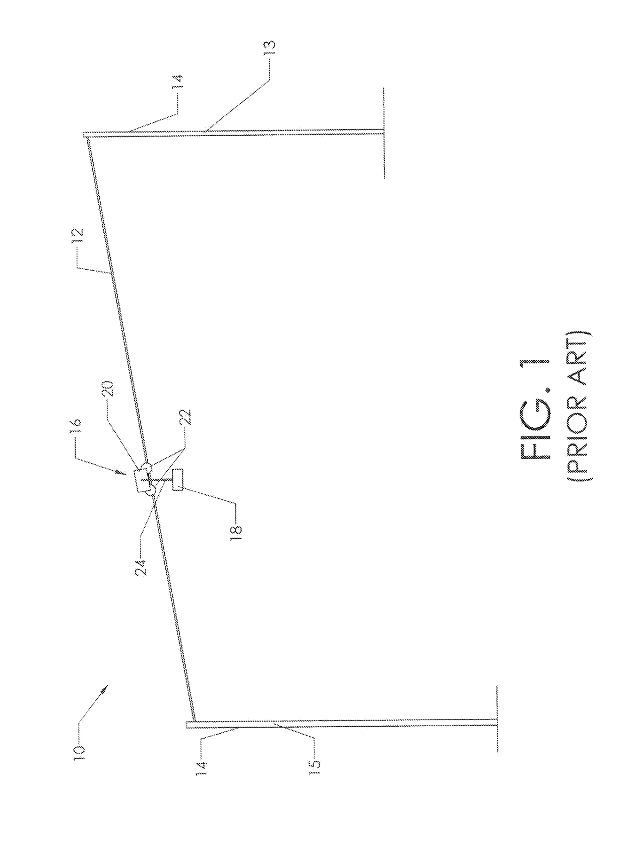
However, this is not a typical configuration. FIG. 1 shows a typical prior art zip line system 10.

Method used


Image

  • Suspended Cable Transportation Vehicle and System
  • Suspended Cable Transportation Vehicle and System
  • Suspended Cable Transportation Vehicle and System

Examples


Embodiment Construction

[0092]The present invention provides a vehicle which is intended to travel along a cable in order to travel from one location to another. As discussed in the preceding text, FIG. 1 shows a prior art zip line system 10. Those familiar with the art will realize that a typical zip line system uses a change in elevation in order to travel along cable 12. Thus, first support 13 is at a higher elevation than second support 15. The vehicle has a starting elevation at first support 13 and an ending elevation at second (or third, fourth, etc.) support. This change from greater elevation to lower elevation allows the rider to travel along cable 12. The reader will note that once the rider reaches second support 15, there may be another support at a lower elevation which he or she then rides to.

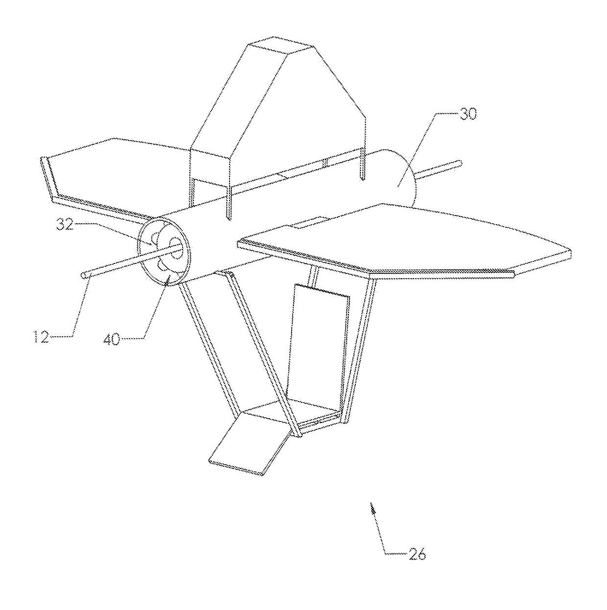
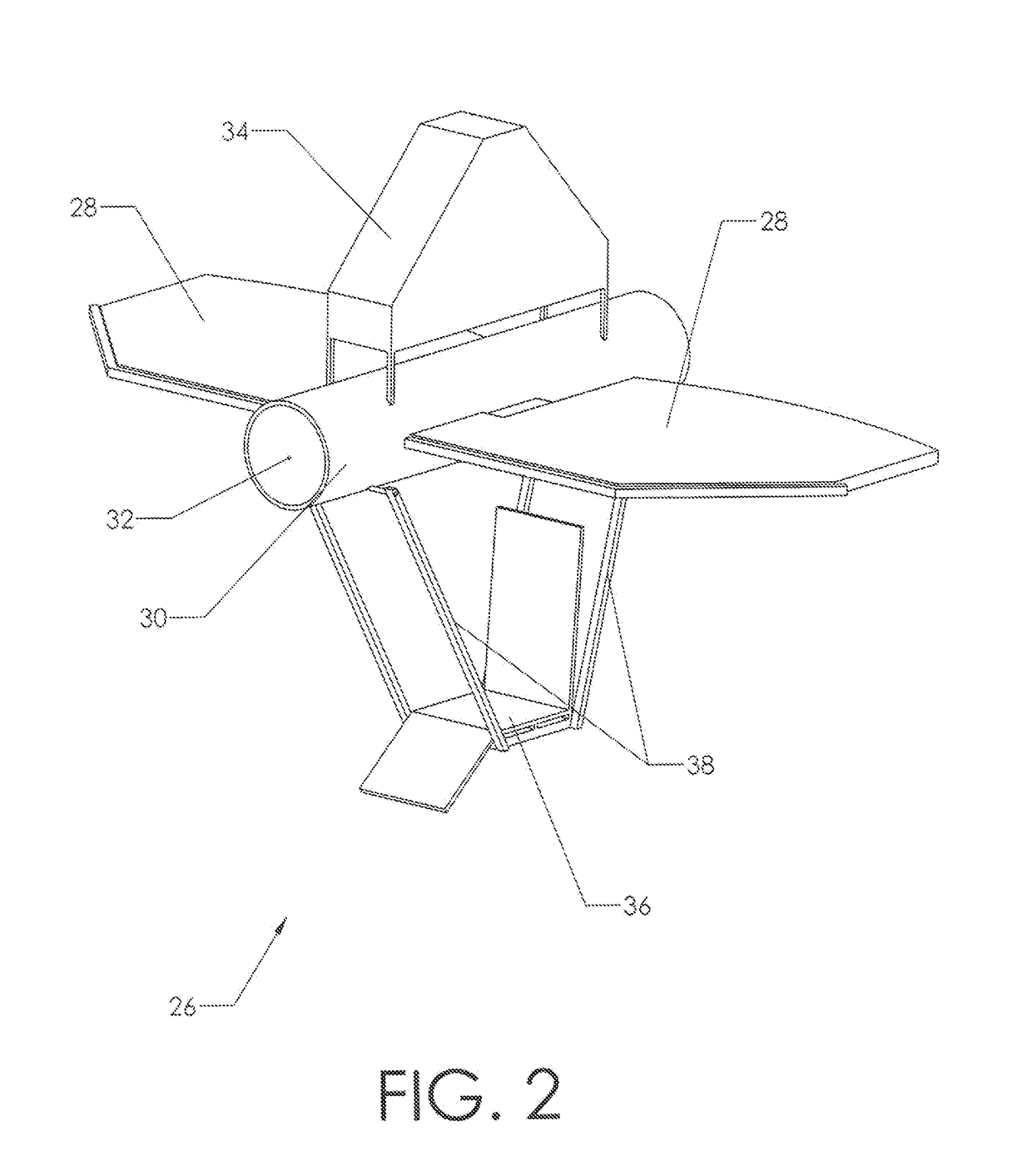
[0093]In a preferred embodiment of the present invention, vehicle 26 includes wings 28, fuselage 30, counterweight system 34, seat 36, and load supports 38. This is shown in FIG. 2. As illustrated, fuse...


PUM


Abstract

A vehicle which is intended to travel along a downward sloping cable, which is suspended between two supports having a change in elevation. Preferably, the vehicle includes a fuselage, a trolley assembly, a translation system, a seat, a counterweight system, and at least one wing. The trolley assembly is attached to the cable. This connection allows the vehicle to travel along the cable. A counterweight system is included in order to balance the weight of the rider sitting in the seat below the fuselage. This allows the vehicle to easily rotate, via rotary joint, around the cable while traveling along the line. Preferably, the rider can induce roll by either activating ailerons or by rotating one of the wings about the lateral axis in order to increase the lift on one side of the aircraft depending on whether the wings are fixed.

Description

CROSS-REFERENCES TO RELATED APPLICATIONS[0001]Not Applicable.STATEMENT REGARDING FEDERALLY SPONSORED RESEARCH OR DEVELOPMENT[0002]Not applicableMICROFICHE APPENDIX[0003]Not ApplicableBACKGROUND OF THE INVENTION[0004]1. Field of the Invention[0005]This invention relates to the field of suspended cable transportation vehicles. More specifically, the invention comprises a vehicle fastened to a downward sloping cable which is suspended between at least two supports.[0006]2. Description of the Related Art[0007]Traveling from one point to another using a suspended cable is well known in the prior art. For example a suspended cable is used to transport skiers from the bottom of a mountain to the top in order to ski down the mountain side. In addition, zip lining uses a downward sloping cable to propel a user along the cable. In both instances an inclined cable is used to transport a rider.[0008]In the case of zip lines, one end of the suspended cable is attached to a point that is vertical...

Claims


Application Information

Patent Timeline
IPC IPC(8): B61B12/12B61B7/00B61D17/02A63G21/20
CPCB61B12/122B61D17/02B61B7/00A63G21/20A63G21/22
Inventor LOUWSMA, KEVIN
Owner LOUWSMA KEVIN
Learn More