Moving object thermometer

Inactive Publication Date: 2011-04-07
TAKIKAWA ENG
View PDF13 Cites 0 Cited by
  • Summary
  • Abstract
  • Description
  • Claims
  • Application Information

AI Technical Summary

Benefits of technology

[0026](i) A moving object thermometer according to the present invention has portions of a first metallic wire and a second metallic wire (hereinafter the both may be collectively referred to as “metallic wire”) disposed on the outer circumferential surface of a disk so as to be inclined toward the shaft center of the disk. For this reason, when a measurement object that is travelling and conductive contacts with the disk, the disk rotates, and resultant contact of the measurement object with the first metallic wire and the second metallic wire causes the first metallic wire and the second metallic wire to be short-circuited with each other, thereby allowing measurement of the surface temperature of the narrowest (thinnest) measurement object (or that having the smallest conductor diameter). Since it is not necessary to make the distance between the first metallic wire and the second metallic wire smaller than the width of the measurement object (conductor diameter), no short-circuit failure will result even if metallic powder or the like is present. Also, the first metallic wire and the second metallic wire can be disposed on the outer circumferential surface of the disk over a wide area ranging from one end face to the other end face, thereby allowing measurement in such a wide area, which enables a moving measurement object to be easily guided (it can be achieved by just providing flanges along both end faces of the disk, for example, by just using a V-shaped pulley-like disk having a flat bottom). Furthermore, the disk is formed of an insulating material, but no limitations are placed on the material, thereby attaining a reduction in weight and thermal capacity, which allows the disk to easily rotate as well as achieves lighter sliding between the metallic wires and the measurement object. Accordingly, use of thinner metallic wires can be implemented, which results in reduction in thermal capacity and frictional heat and prevention of wear and metallic powder generation, leading to enhanced measurement accuracy and prolonged durability of the equipment.
[0027](ii) Also, the moving object thermometer according to the present invention has portions of the first metallic wire and the second metallic wire disposed side by side in a zig-zag manner on the outer circumf

Problems solved by technology

(a) However, the invention disclosed in Japanese Unexamined Patent Application Publication No. 7-72021 leads to a problem that it is difficult to measure the surface temperature of, particularly, a small-diameter metallic wire that is moving (or travelling).
Consequently, difficulties in guiding a travelling metallic wire to an exact position have been encountered or a short-circuit failure caused by metallic powder falling on the approximated dissimilar metals (same as a conductive rotary roller) have been experienced.
(b) Also, when temp

Method used


Image

  • Moving object thermometer
  • Moving object thermometer
  • Moving object thermometer

Examples


Example

Moving Object Thermometer

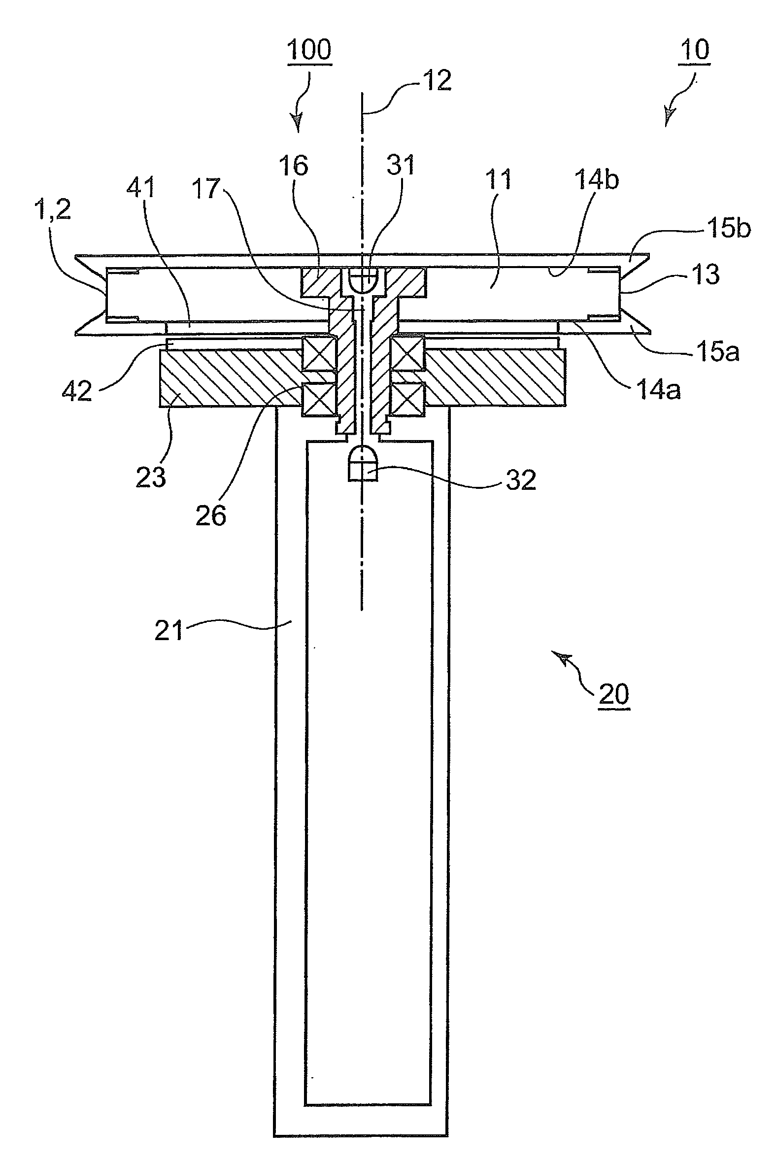
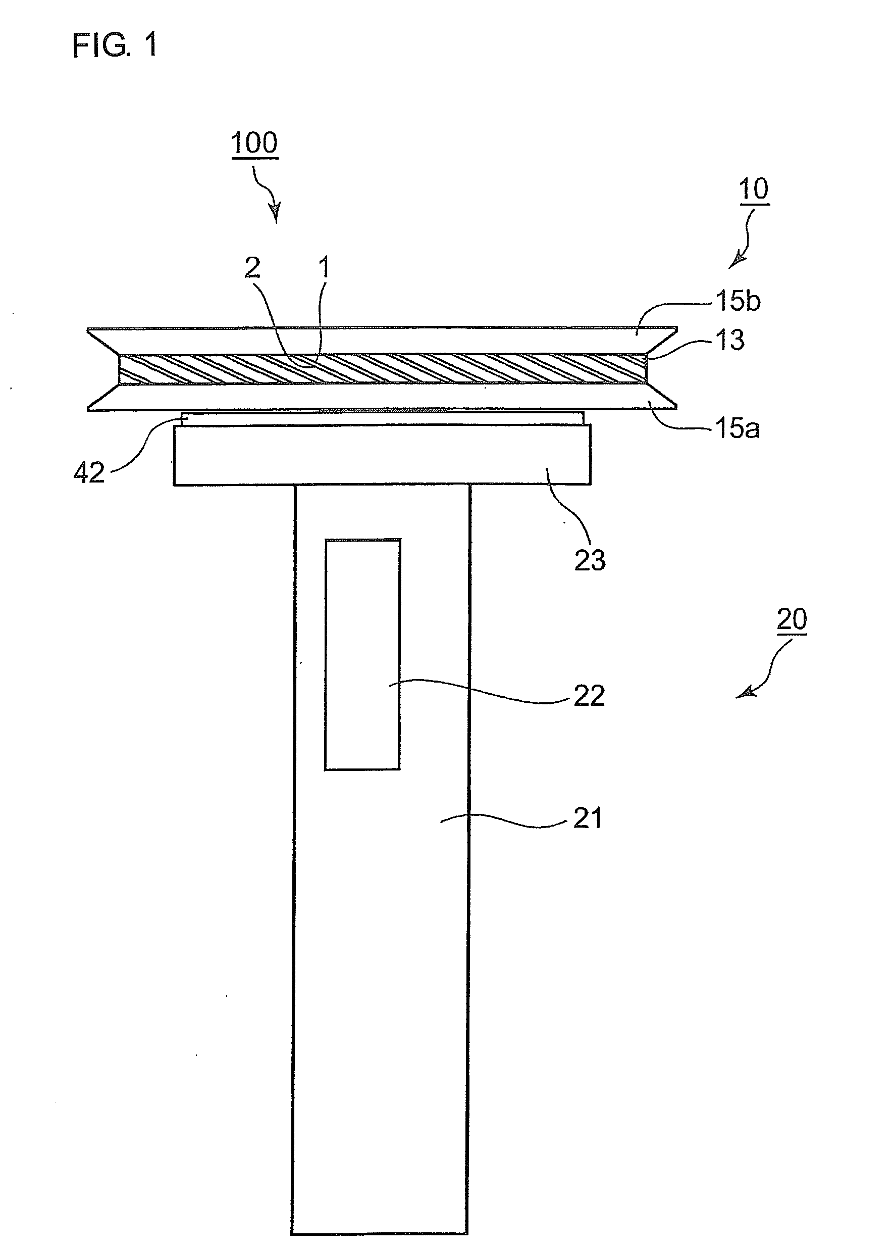
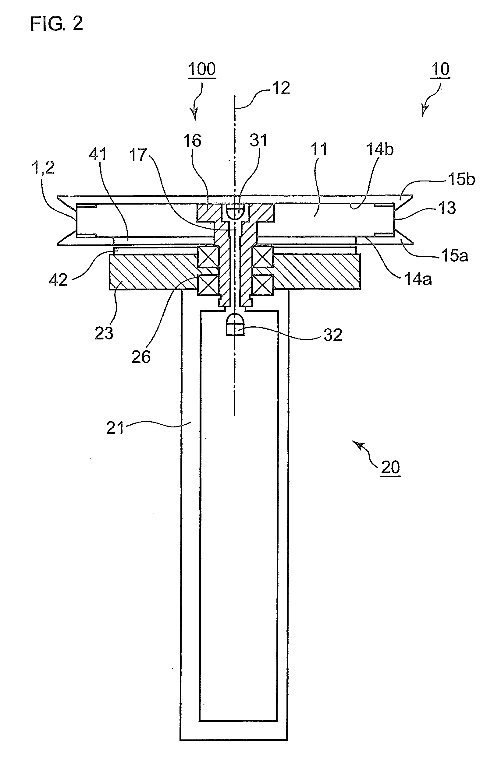
[0038]FIGS. 1 through 4 are views for explaining a moving object thermometer according to Embodiment 1 of the present invention. FIG. 1 is a front view illustrating the external appearance. FIG. 2 is a cross-sectional view when viewed from front. FIG. 3 is a circuit diagram showing the electrical configuration. FIG. 4 is a partly cross-sectional front view showing part (placement of metallic wires) of the moving object thermometer. These figures are schematically drawn views, and the present invention is not limited to the foregoing preferred embodiments. Various modifications are conceivable within the scope of the present invention. In FIGS. 1 and 2, a moving object thermometer 100 has a rotary section (same as a measuring section) 10 and a stationary section 20 that rotatably supports the rotary section 10.

(Rotary Section)

[0039]The rotary section 10 includes a disk 11 formed of an insulating material (synthetic resin) and a first metallic wire 1 (chromel ...


PUM


Abstract

A moving object thermometer is provided which can precisely measure the surface temperature of a moving (travelling) measurement object, particularly, a small-diameter conductive wire. A first metallic wire 1 and a second metallic wire 2 constituting a thermocouple are disposed on the outer circumferential surface 13 of the disk 11 in the rotary section 10 so as to be inclined toward the shaft center. A thermoelectric force resulting from contact of the metallic wires with a measurement object is converted into an electric signal, which is transmitted through the light emitting diode 31 and passed to the photodiode 32 provided at the stationary section 20 in a non-contact manner. Application of a high frequency current to the stationary side coil 42 provided at the stationary section 20 causes electric power to be supplied in a non-contact manner to the rotary side coil 41 provided so as to be opposed to the stationary side coil 42.

Description

BACKGROUND OF THE INVENTION[0001]1. Field of the Invention[0002]The present invention relates to a moving object thermometer and, more particularly, to a moving object thermometer for measuring the surface temperature of a travelling or rotating metallic body (such as a metallic wire).[0003]2. Description of the Related Arts[0004]Conventionally, moving object thermometers for measuring the surface temperature of a travelling or rotating conductive body such as a metallic body are disclosed in, for example, Patent Document 1 in which a pair of conductive rotary rollers, each rotatably supported by a sliding bearing, are integrated into one unit with an insulator therebetween and are wrapped at its outer circumferential surface with a thermocouple dissimilar metal, thereby causing the outer circumferential surface of the rotary roller to contact with the travelling (rotating) measurement object in order to generate a thermoelectric force in the dissimilar metal, which is inputted to a...

Claims


Application Information

Patent Timeline
IPC IPC(8): G01K7/02
CPCG01K13/06G01K7/04G01K13/08
Inventor TAKIGAWA, KATSUNOBUSAKAMOTO, YASUFUMI
Owner TAKIKAWA ENG
Why Eureka
Try Eureka