Electronic apparatus

Inactive Publication Date: 2010-02-04
EPSON IMAGING DEVICES CORP
View PDF2 Cites 3 Cited by
  • Summary
  • Abstract
  • Description
  • Claims
  • Application Information

AI Technical Summary

Benefits of technology

[0024]In such a case, the display area of the display panel of the electro-optical device can be easily rotated to the reference po

Problems solved by technology

Thus, a lot of spacers must be arranged on the bottom face, and accordingly, there is a problem from the viewpoint of the

Method used


Image

  • Electronic apparatus
  • Electronic apparatus
  • Electronic apparatus

Examples


Example

First Embodiment: Thin-type Large Screen TV

[0048]Hereinafter, a thin-type large screen TV as an electronic apparatus according a first embodiment of the invention will be described.

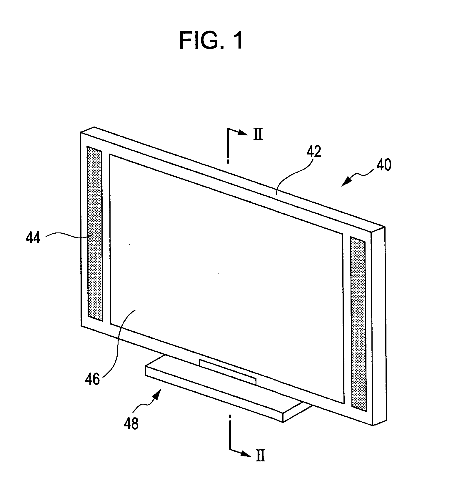
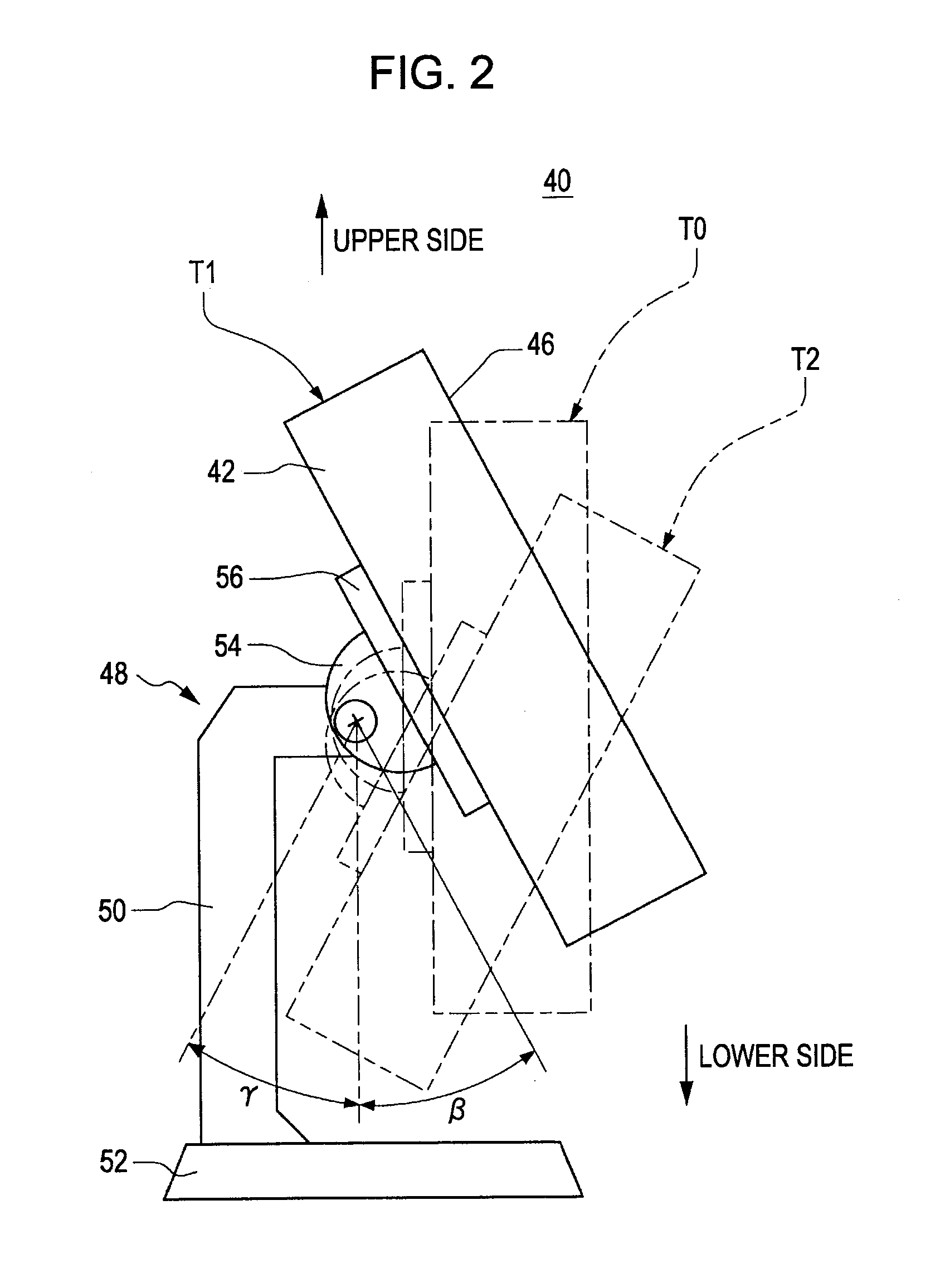
[0049]FIG. 1 is a perspective view of the thin-type large screen TV according to this embodiment. FIG. 2 is a cross-sectional view taken along line II-II shown in FIG. 1. FIG. 3 is a diagram showing a front face of the thin-type large screen TV according to this embodiment, viewed in the horizontal direction.

[0050]The thin-type large screen TV (electronic apparatus) 40, as shown in FIG. 1, includes a thin-type large screen TV main body 42, a voice outputting unit 44 such as a speaker, a display unit 46 for the thin-type large screen TV to which a liquid crystal display device to be described later is applied, and a support device 48 as a support post.

[0051]The display unit 46 according to this embodiment is a liquid crystal display device having a back light unit to be described later.

[0052]In the support...

Example

Second Embodiment: Back Light Unit

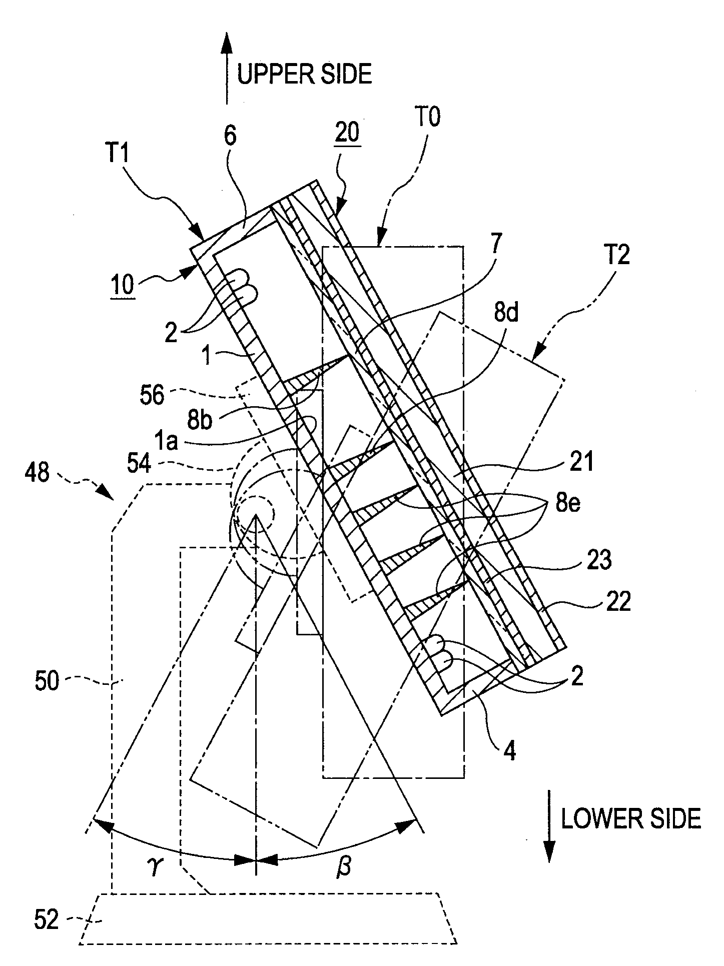
[0055]FIG. 4 is a diagram showing a front face of a back light unit according to a second embodiment of the invention, viewed in the horizontal direction. FIG. 5 is a cross-sectional view taken along line V-V shown in FIG. 4 and is a diagram showing a back light unit that is disposed to be parallel to the direction of gravity or is inclined upward or downward with respect to the direction of gravity. FIG. 6 is a diagram showing a back light unit that is inclined upward with respect to the direction of gravity without arranging any spacers.

[0056]The back light unit 10 according to this embodiment, as shown in FIG. 4, includes a casing 1 of a bottomed-box shape, a plurality of light sources 2 arranged in a plurality of rows on a bottom face 1a of the casing 1 with a predetermined gap interposed therebetween, a diffusion plate (optical member) 7 that is fixed to a plurality of side walls 3 to 6 that are vertically arranged from an edge portion of the c...

Example

Third Embodiment: Back Light Unit

[0063]FIG. 7 is a diagram showing a front face of a back light unit according to a third embodiment of the invention, viewed in the horizontal direction.

[0064]According to the back light unit 10 of this embodiment which is arranged to be inclined upward with respect to the direction of gravity, one spacer 11 is arranged on the bottom face 1a in a position F in which the flexural amount of the lower half area S2 of the face of the diffusing plate 7 with respect to the direction of gravity is increased.

[0065]According to this embodiment, the number of spacers is decreased greatly (one spacer 11), and accordingly, the time required for the operation for arranging the spacer 11 can be shortened greatly, and accordingly the manufacturing cost of the back light unit 10 can be reduced further.

[0066]In addition, the flexure of the diffusing plate 7 can be suppressed since the spacer 11 is arranged in the position F in which the flexural amount of the lower h...


PUM


Abstract

An electronic apparatus includes a back light unit that has a light source, an optical member that is arranged so as to face the irradiation direction of the light of the light source, and a spacer that supports the optical member from the light source side and is arranged in a state in which the optical member is arranged parallel to the direction of gravity or inclined with respect to the direction of gravity, and a display panel that is arranged so as to be superimposed on the optical member of the back light unit. In the back light unit, the number of spacers arranged in an upper half area of the optical member with respect to the direction of gravity is configured to be smaller than that of the spacers arranged in a lower half area of the optical member with respect to the direction of gravity.

Description

BACKGROUND[0001]1. Technical Field[0002]The present invention relates to an electronic apparatus including an electro-optical device that uses a direct-below-type back light unit having a spacer that supports an optical member.[0003]2. Related Art[0004]Generally, liquid crystal display (LCD) devices include a display panel that displays an image and a back light unit that is arranged on a rear face of the display panel and irradiates light toward the display panel.[0005]Recently, the size of the screens of the liquid crystal display devices that are commonly used as the display devices of personal computers and CAD apparatuses has increased. Accordingly, luminance that is not inferior to that of display devices using Braun tubes is required for the large-screen liquid crystal display devices.[0006]The large-screen liquid crystal display devices are commonly used on a table, on the floor, or the like as a stationary-type device, and thus a decrease in the thickness of the liquid crys...

Claims


Application Information

Patent Timeline
IPC IPC(8): G02F1/13357G02F1/1333
CPCG02F1/133608G09F13/04G02F1/133606F21V14/02H04N9/12
Inventor NAKANISHI, DAISUKE
Owner EPSON IMAGING DEVICES CORP
Why Eureka
Try Eureka