Protective cover for a valve

Inactive Publication Date: 2009-09-10
BORNE LYNN ERIC
View PDF18 Cites 3 Cited by
  • Summary
  • Abstract
  • Description
  • Claims
  • Application Information

AI Technical Summary

Benefits of technology

[0011]The present invention solves these problems by providing a protective cover apparatus for a control valve that is able to be engaged around a very wide range of valves. The protective cover includes a pair of cylinders, each having a closed end and an open end. An inner one of the cylinders has a cut-away portion in its side wall which extends between its open end and its closed end, and its closed end is also cut-away wherein these cutaway portions are contiguous. The outer cylinder has a slot in its side wall which extends from its open end to a medial point on its side wall. The inner cylinder, by virtue of its cut-away portions, is easily slid over a supply pipe extending from a wall or floor surface so that the axes of the inner cylinder and the supply pipe are congruent. The closed end of the inner cylinder is preferably screwed to the wall or floor surface.
[0012]Normally, a valve, of the type referred to here, is joined to the terminal end of the supply pipe, which, as mentioned, extends thr

Problems solved by technology

The valve handle is usually exposed and unprotected, thereby subjecting it, the valve stem and the valve, to potential damaging contact.
However, such inventio

Method used


Image

  • Protective cover for a valve
  • Protective cover for a valve
  • Protective cover for a valve

Examples


Example

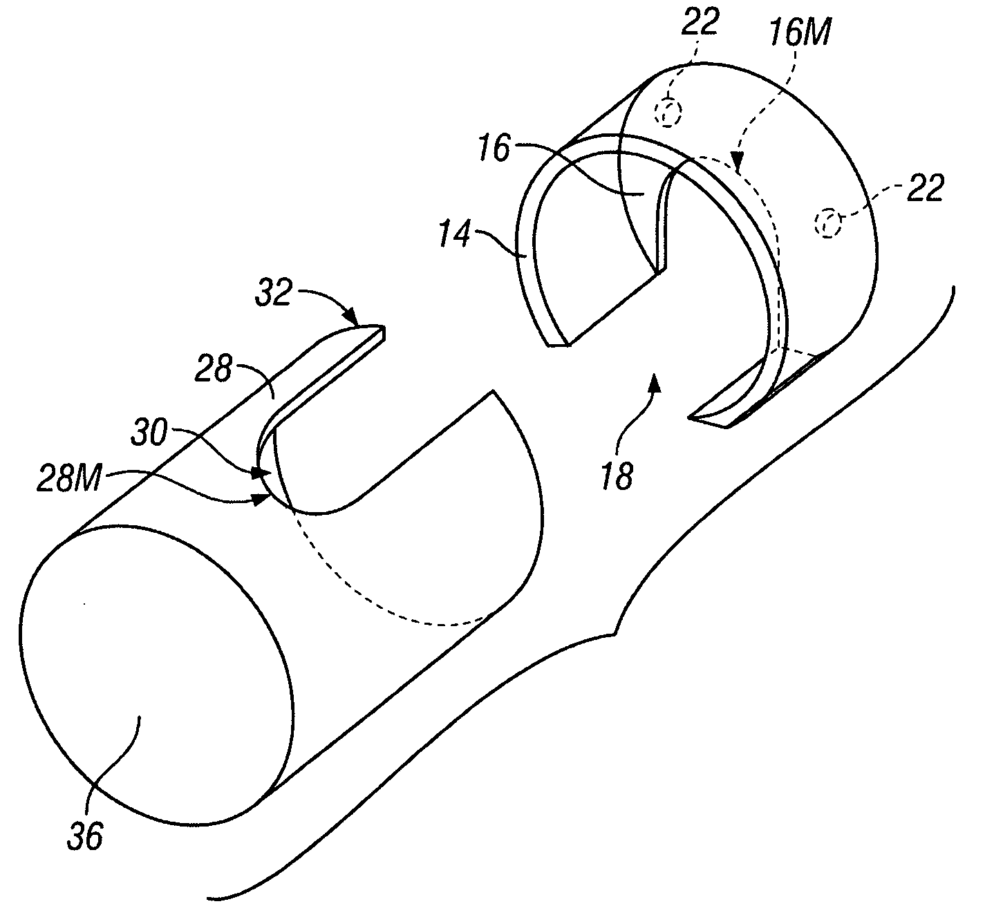
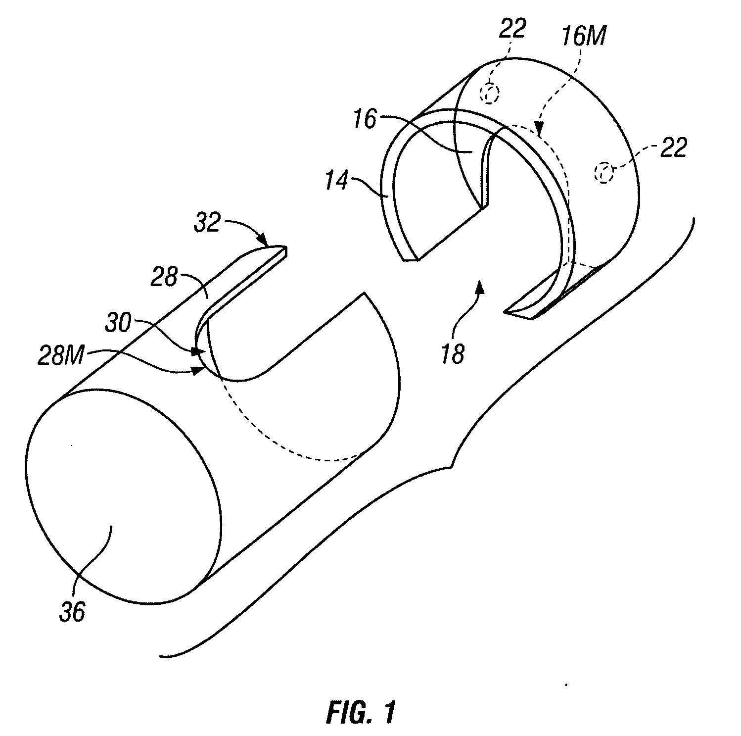
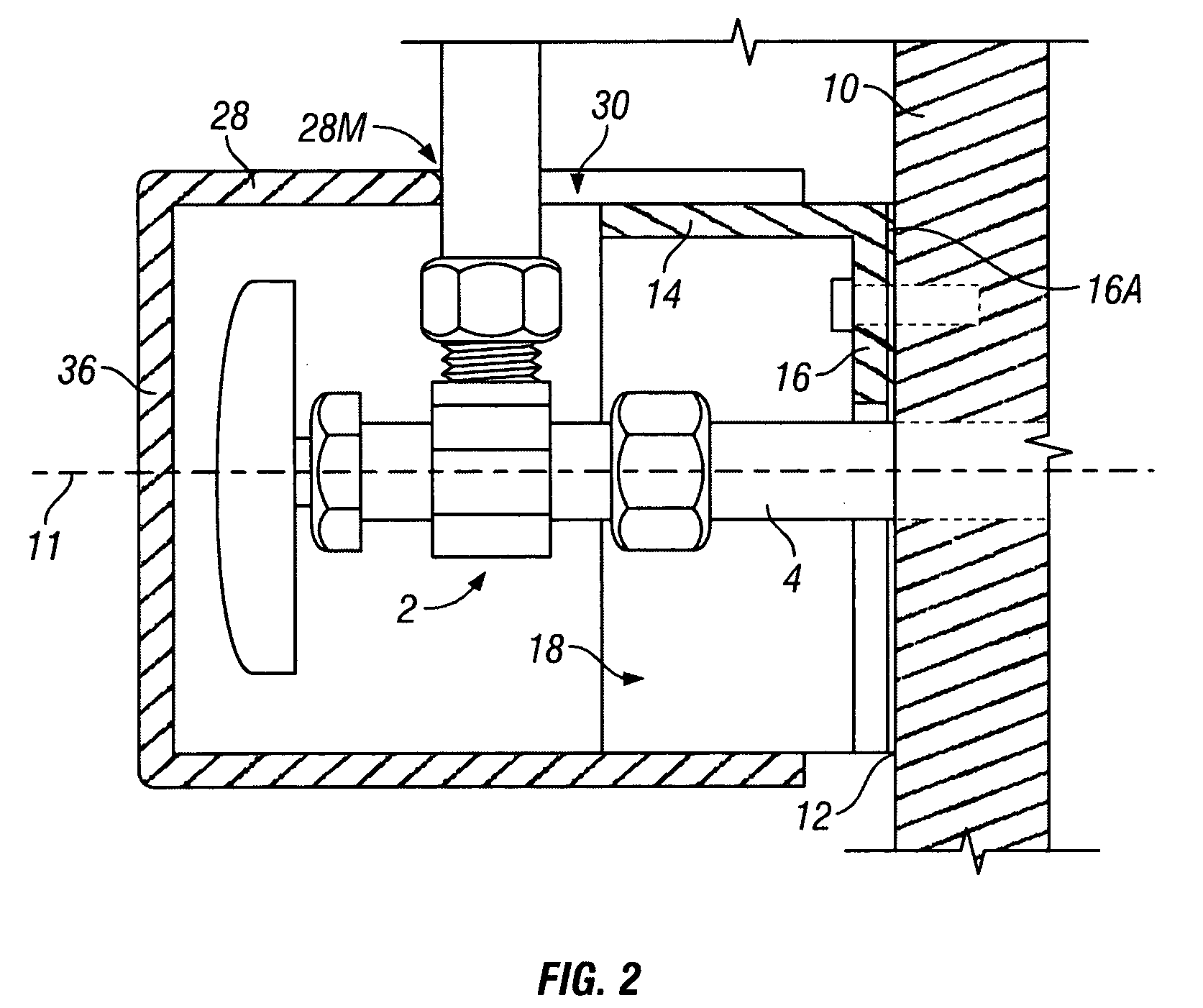
[0025]In a first embodiment shown in FIGS. 1 and 2, the apparatus provides a base cylinder wall 14 aligned with the longitudinal axis 11 and terminating distally with an integral base end wall 16. The base cylinder wall 14 has a base slot 18 extensive longitudinally therethrough. The slot 18 is contiguous through the base end wall 16 radially to a medial position 16M in the base end wall 16. This is clearly shown in FIG. 1.

[0026]A cover cylinder wall 28 is aligned with the longitudinal axis 11 and frictionally engaged with the base cylinder wall 16 as shown in FIG. 2. The cover cylinder wall 28 has a cover slot 30 extensive longitudinally therethrough from a distal end 32 of the cover cylinder wall 28 to a medial position 28M therein. The cover cylinder wall 28 preferably has a proximal cover end wall 36 integral with the cover cylinder wall 28 as shown in FIGS. 1 and 2, but the end wall 36 may be omitted as shown in FIGS. 3 and 4.

[0027]The base end wall 16 preferably has a means fo...

Example

[0028]In a second embodiment of the present invention, shown in FIGS. 3 and 4, the base cylinder wall 14 and base end wall 16 are replaced by a base block 140. The base block 140 has an outer surface 142 and an opposing concave inner surface 144, wherein the outer and inner surfaces 142 and 144 are longitudinally extensive between a distal 146 and a proximal 148 planar surfaces. The base block 140 has the shape of an inverted “U” as is clearly shown in FIG. 3.

[0029]The same cover cylinder wall 28 as described in the first embodiment above is also used here in the second embodiment. The cover cylinder wall 28 is aligned with the longitudinal axis, as before, and is frictionally engaged with the outer surface 142 of the base block 140. The adhesive 12 may be applied to base block surface 146 to mount the base block 140 to wall surface 10 as above. Alternately, the base block may have mounting holes therethrough, extensive between the distal 146 and proximal 148 planar surfaces.

[0030]T...


PUM


Abstract

A protective cover for a valve which is mounted proximally on an inlet pipe extending from a distal wall surface along a longitudinal axis provides a base cylinder wall aligned with the longitudinal axis and terminating distally with an integral base end wall. The base cylinder wall has a base slot extensive longitudinally, the slot contiguous through the base end wall radially to a medial position. a cover cylinder wall aligned with the longitudinal axis and frictionally engaged with the base cylinder wall; the cover cylinder wall having a cover slot extensive longitudinally therethrough from a distal end of the cover cylinder wall to a medial position therein. In an alternate embodiment, the base cylinder wall and end wall are replaced by a block with a longitudinal recess.

Description

BACKGROUND OF THE INVENTION[0001]1. Field of the Present Disclosure[0002]This disclosure relates generally to protective valve covers and, in particular, to a removable valve cover which is placed over an under-sink supply valve to protect the valve from damaging contact by the movement of items stored in the same space.[0003]2. Description of Related Art Including Information Disclosed Under 37 CFR 1.97 and 1.98[0004]Woebbeking, US 2768766, discloses a cover for the free end of a faucet comprising a cylindrical cap having a sidewall and an end wall, said end wall having an inward side and outer end, a resilient strip secured to and extending across said inward side of the end wall and across said inner end of the sidewall, said strip terminating at its ends and outside of said sidewall in resilient fingers extending in a direction away from said end wall, said sidewall having openings registered with said fingers, said fingers having portions reaching through said openings for enga...

Claims


Application Information

Patent Timeline
IPC IPC(8): B65D25/00
CPCE03C1/021
Inventor BORNE, LYNN ERIC
Owner BORNE LYNN ERIC
Why Eureka
Try Eureka