Milling insert and a milling tool

Active Publication Date: 2017-11-16
SANDVIK INTELLECTUAL PROPERTY AB
View PDF16 Cites 4 Cited by
  • Summary
  • Abstract
  • Description
  • Claims
  • Application Information

AI Technical Summary

Benefits of technology

[0029]According to an embodiment of the invention, an empty space is provided in the tool body radially inside of the milling insert and in connection with the insert seat, so that the side surface of the milling insert opposite the primary clearance surface is not in co

Problems solved by technology

A problem with milling inserts having through-holes for receiving a fastening member is that pressing can leave a variation in the de

Method used


Image

  • Milling insert and a milling tool
  • Milling insert and a milling tool
  • Milling insert and a milling tool

Examples


Embodiment Construction

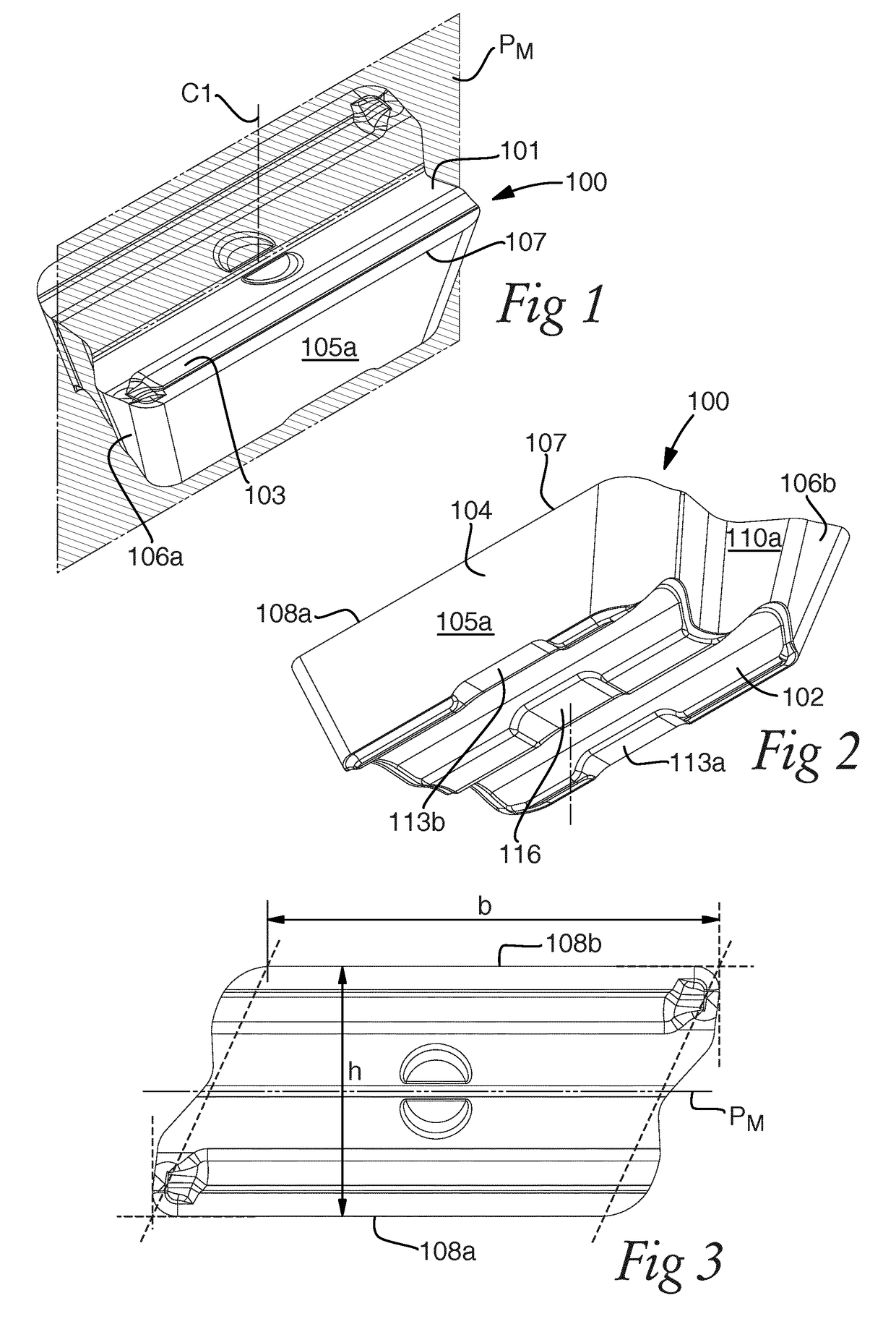
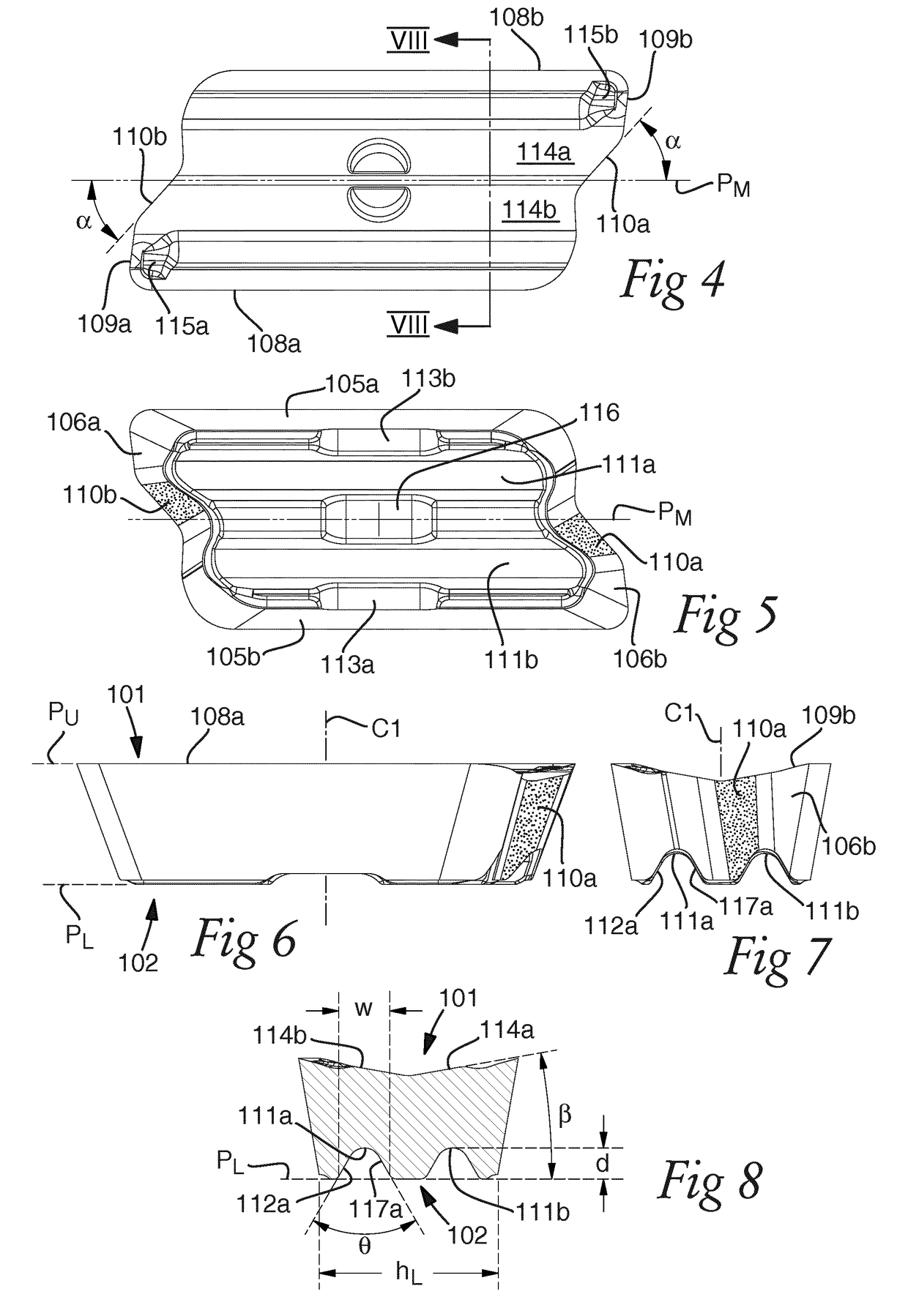
[0048]FIGS. 1-8 show a milling insert 100 according to the invention. The milling insert 100 is in the shown embodiment an indexable milling insert adapted for shoulder milling at an entering angle of 90°. The milling insert 100 comprises an upper side 101 and an opposite lower side 102, between which sides a central axis C1 extends. An upper extension plane PU and a lower extension plane PL parallel with the upper extension plane PU, defined by the upper side 101 and the lower side 102 respectively, limit the milling insert 100 in the direction of the central axis C1. The upper side 101 includes a chip surface 103. A side surface 104 extends between the upper side 101 and the lower side 102 around the periphery of the milling insert 100 and includes in the shown embodiment two primary clearance surfaces 105a, 105b and two secondary clearance surfaces 106a, 106b. A cutting edge 107 extends around the upper side of the milling insert 100, including two chip removing primary cutting e...


PUM


Abstract

A milling insert suitable for shoulder milling includes a side surface extending between an upper and lower side and a cutting edge having a primary and a secondary cutting edge portion. The side surface includes an axial support surface opposite of the secondary cutting edge portion. The lower side includes a locking groove extending longitudinally, and a lower contact region formed to bear on a fastening member. The upper side has an upper contact region arranged to bear on a top support member of a tool in which the milling insert is mountable. A milling tool is provided with a top support member for bearing on the upper contact region of the milling insert, a locking ridge for locking with the locking groove, and an axial contact surface for supporting the axial support surface. A fastening member presses the milling insert against the top support member and the locking ridge.

Description

TECHNICAL FIELD OF THE INVENTION[0001]The present invention relates to a milling insert according to the preamble of claim 1. It further relates to a milling tool according to the preamble of claim 11. In particular, the milling tool and the milling insert are suitable for use in shoulder milling applications.BACKGROUND OF THE INVENTION AND PRIOR ART[0002]Milling tools for shoulder milling, such as shank-end mills, may advantageously be used for machining of shoulders, grooves and edges. For the machining of small details, it is necessary to use a milling tool having a small diameter. For cost-efficiency, it is preferable to use a milling tool which comprises on one hand a tool body, and on the other hand detachable and replaceable milling inserts. However, the milling inserts are subjected to great forces during the milling operation, acting to displace and turn the milling inserts. It is therefore necessary to rigidly fasten the milling inserts in the tool body. This is most often...

Claims


Application Information

Patent Timeline
IPC IPC(8): B23C5/10B23C5/20B23C5/22
CPCB23C5/109B23C5/207B23C5/22B23C2200/0438B23C2200/165B23C2200/286B23C2210/168B23C2210/165B23C5/202Y10T407/192B23C5/205B23C5/2304B23C2200/287B23B27/16B23C5/20
Inventor PETTERSSON, SVENKAKAI, ISAK
Owner SANDVIK INTELLECTUAL PROPERTY AB
Why Eureka
Try Eureka