Downhole tool with protective covering

Inactive Publication Date: 2019-08-29
MAGNUM OIL TOOLS INT
View PDF6 Cites 2 Cited by
  • Summary
  • Abstract
  • Description
  • Claims
  • Application Information

AI Technical Summary

Benefits of technology

[0014]Sand often accumulates on the bottom of the casing of a well's horizontal leg. The entire wellbore has sand and it typically falls out of the downhole fluid, ultimately being deposited in the bottom of the horizontal legs. The accumulated sand on the bottom of horizontal legs creates destructive abrasion and friction upon downhole tools as they are forced through the sand filled horizontal leg for completion and recompletion operations. In an embodiment, the covering is adapted to protect the tool from destructive sand friction as the tool slides through sand on the bottom of the wells horizontal leg. The wrap is adapted to make the covered tool smooth and strong enough to enable the covered tool to more easily slide through sand on the bottom of a horizontal leg of the well, namely, the cover, in some embodiments, may be longitudinally long enough to cover the tool's radially protruding portions, namely, upper and lower rings, upper and lower slips, upper and lower cones, and seal, and provide, in some embodiments, a smooth covered tool outer surface, and the cover is, in some embodiments, at least 2.0 mil thick for providing resistance against sand abrasion as the covered tool is run in through the horizontal leg. The smooth covering reduces both rotary friction and longitudinal friction of the tool in the casing. Reduced friction, particularly in a long horizontal leg, provides multiple benefits during completion and recompletion of longitudinal legs.
[0015]To provide longitudinal smoothness to best reduce longitudinal friction and help avoid inadvertent preset during run in, in some embodiments, the wrap does not tightly cling to the entire tool outer surface, but rather comprises a smoother outer covering about the tool's radially irregular surface comprised of its rings, slips, cones and elastomeric seal having different radial dimensions. The wrap may, for example, cling to the outer radial edges of rings and slips without extending further inward to inner radial surfaces of the tool. In an embodiment, the protective wrap is attached to at least some larger radial outer surfaces of the slip or slips and cone or cones and is not attached to some smaller radial outer surfaces of the slip or slips and cone or cones, and the protective wrap provides a covered tool outer surface which is smoother than a similar tool without the wrap. A tool with this type of covering is capable of sliding through a horizontal leg of the well having debris on the bottom of the horizontal leg with less friction through debris and thus horizontal force than a similar tool without such a smooth wrap.
[0016]Adapting the covering to survive casing caused and sand caused friction, abrasion and tearing requires selection of appropriate covering materials and covering thicknesses. In an embodiment, the covering is between 0.5 to 7 mil thick, in another between 1.5 to 5 mil, and in another between 2 to 3.5 mil thick. Preferable thickness may be a function of anticipated sand friction and erosion on the frac plugs, sand infiltration of the frac plugs, duration between insertion of the frac plug into the downhole fluid and the setting tool setting, sharpness of the slips inserts and withers, manufacturing limitations and conveniences, and other considerations. Protection against abrasion on a tool caused by sliding on the bottom of horizontal leg or by sand in the bottom of horizontal leg when the tool is to be moved through a horizontal leg, and reduction of friction when a tool is to be moved through a horizontal leg having sand or other debris on the bottom of the leg is somewhat obtainable by using a thicker covering. To protect against abrasion and friction a covering may be 5 mil, or 4 mil or 3 mil thick, as the abras

Problems solved by technology

Boxed, crated and palleted tools are subject to humidity during storage and transport.
This may be particularly disadvantageous for tools which are subject to degradation due to humidity.
Well sites are often littered with scores of discarded cardboard boxes, crates and pallets which were used to deliver downhole tools for use at the well.
Consumption of boxes, cr

Method used


Image

  • Downhole tool with protective covering
  • Downhole tool with protective covering
  • Downhole tool with protective covering

Examples


Example

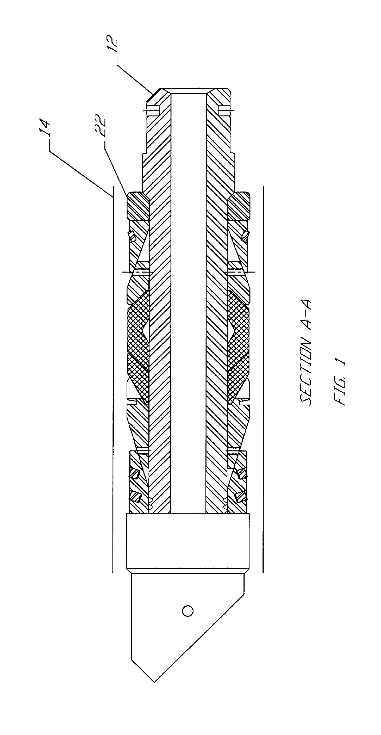
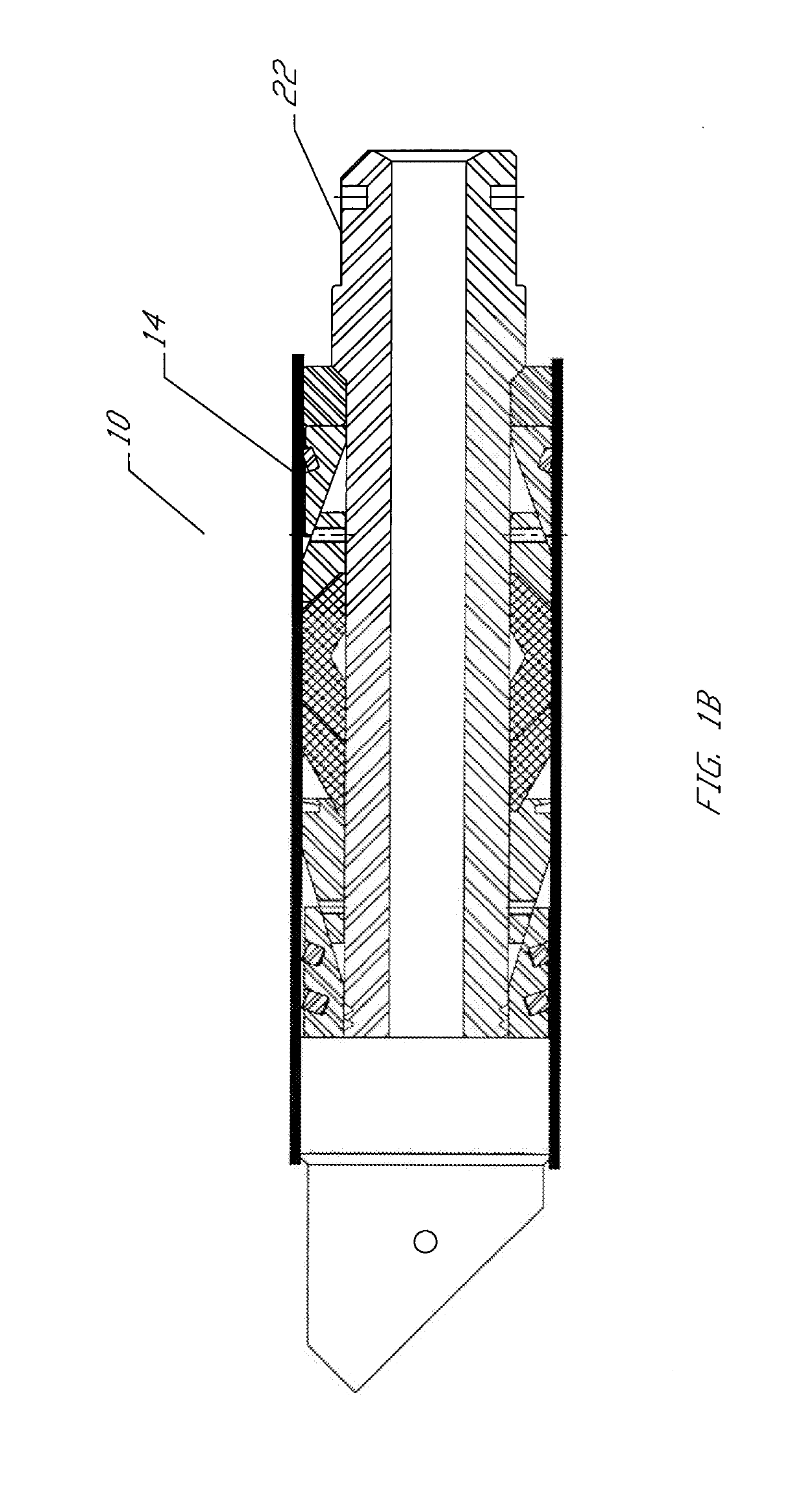
[0040]FIG. 1 illustrates downhole tool 12 having an outer surface 22, including sidewall 12a, bottom wall 12b and top wall 12c (see FIG. 3C) at least partially covered by an unshrunk wrap 14. FIG. 1 illustrates a preshrunk wrap about the tool. FIG. 1A illustrates a wrap shrunk tight about the tool so the wrap follows the contours of the outer surface of the tool. FIG. 1B illustrates the wrap in a smooth shrunk condition, achieved by using less heat than used to achieve the shrink tight configuration of FIG. 1A and useful in some embodiments as further described herein.

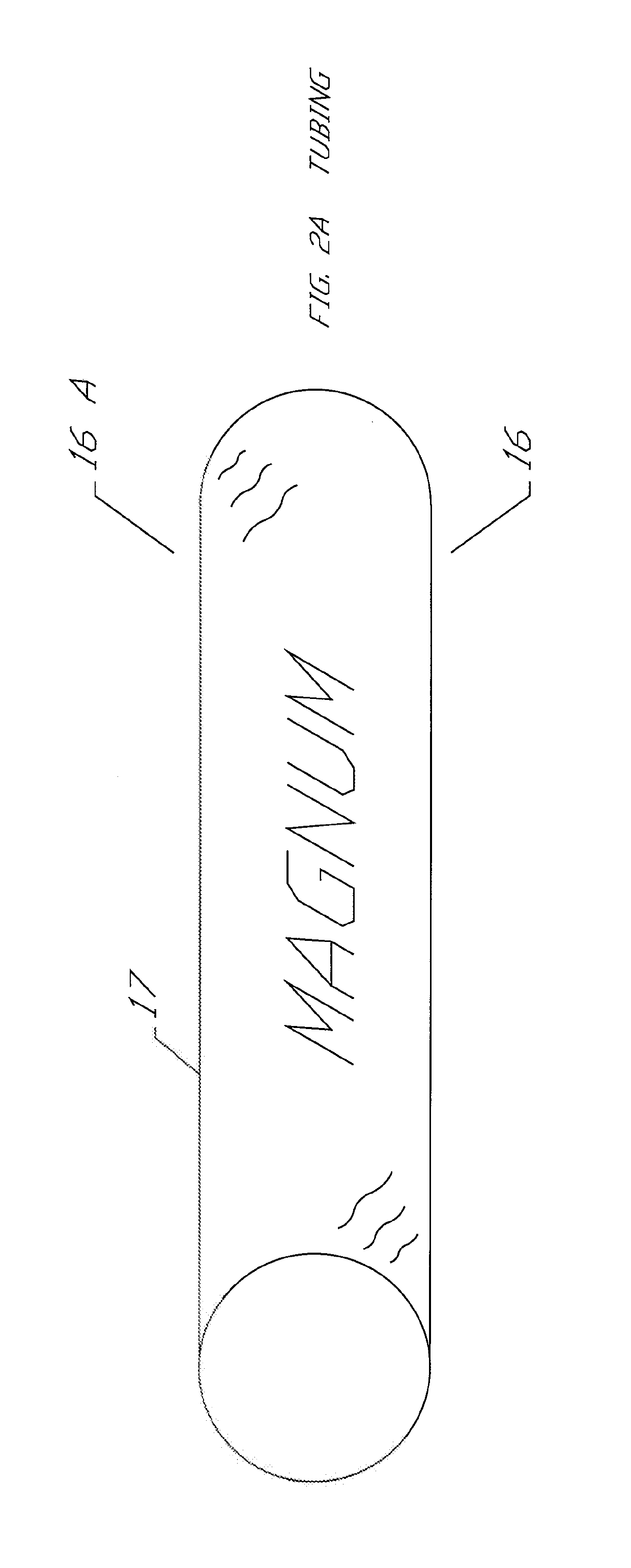
[0041]FIGS. 2A, 2B and 2C illustrate three forms of heat shrinkable material that may be used to form a wrap 14. FIG. 2A illustrates a heat shrink material comprising a sleeve or tube 16 (open at both ends), typically cylindrical, and, in some embodiments, somewhat stiff, and having a diameter selected to receive the tool therein. In FIG. 2A, the tube has indicia 17 on its surface, the indicia including, for example, a...


PUM


Abstract

Degradable and abradable protective covers closely fitted about degradable downhole tools, and methods and devices for making, packaging, transporting and using degradable downhole tools with such covers.

Description

[0001]This application claims the benefit of, priority to, and incorporates herein by reference U.S. Provisional Application No. 62 / 635,713, filed Feb. 27, 2018 and U.S. Provisional Application No. 62 / 658,736, filed Apr. 17, 2018. U.S. patent application Ser. No. 15 / 355,346, filed Nov. 18, 2016, and Ser. No. 16 / 182,206, filed Nov. 6, 2018, are incorporated herein by reference.FIELD OF THE INVENTION[0002]The field of invention is manufacturing, storage, transportation and use of downhole tools, including downhole tools with a protective cover. Embodiments of degradable and abradable protective covers closely fitted about downhole tools, and methods and devices for making, packaging and using downhole tools with such covers are disclosed. Protective covers for downhole tools to help protect the downhole tools in storage, shipment and at the well site from humidity and handling and during use downhole are disclosed. The cover may be a sleeve, bag or sheet applied after the tool is manu...

Claims


Application Information

Patent Timeline
IPC IPC(8): E21B25/02E21B33/12E21B25/06E21B34/06
CPCE21B25/02E21B33/1208E21B2034/007E21B34/063E21B25/06E21B33/12E21B33/134
Inventor FRAZIER, W. LYNN
Owner MAGNUM OIL TOOLS INT
Why Eureka
Try Eureka