

Wireless IC device
- Summary
- Abstract
- Description
- Claims
- Application Information
AI Technical Summary
Benefits of technology
Problems solved by technology
Method used
Image

Examples
first preferred embodiment
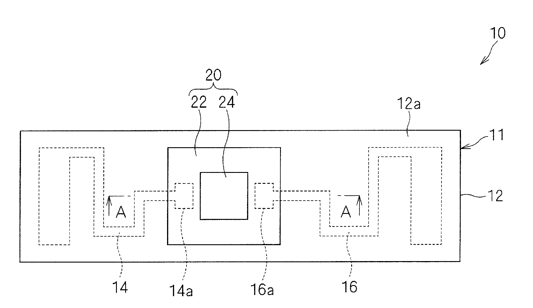
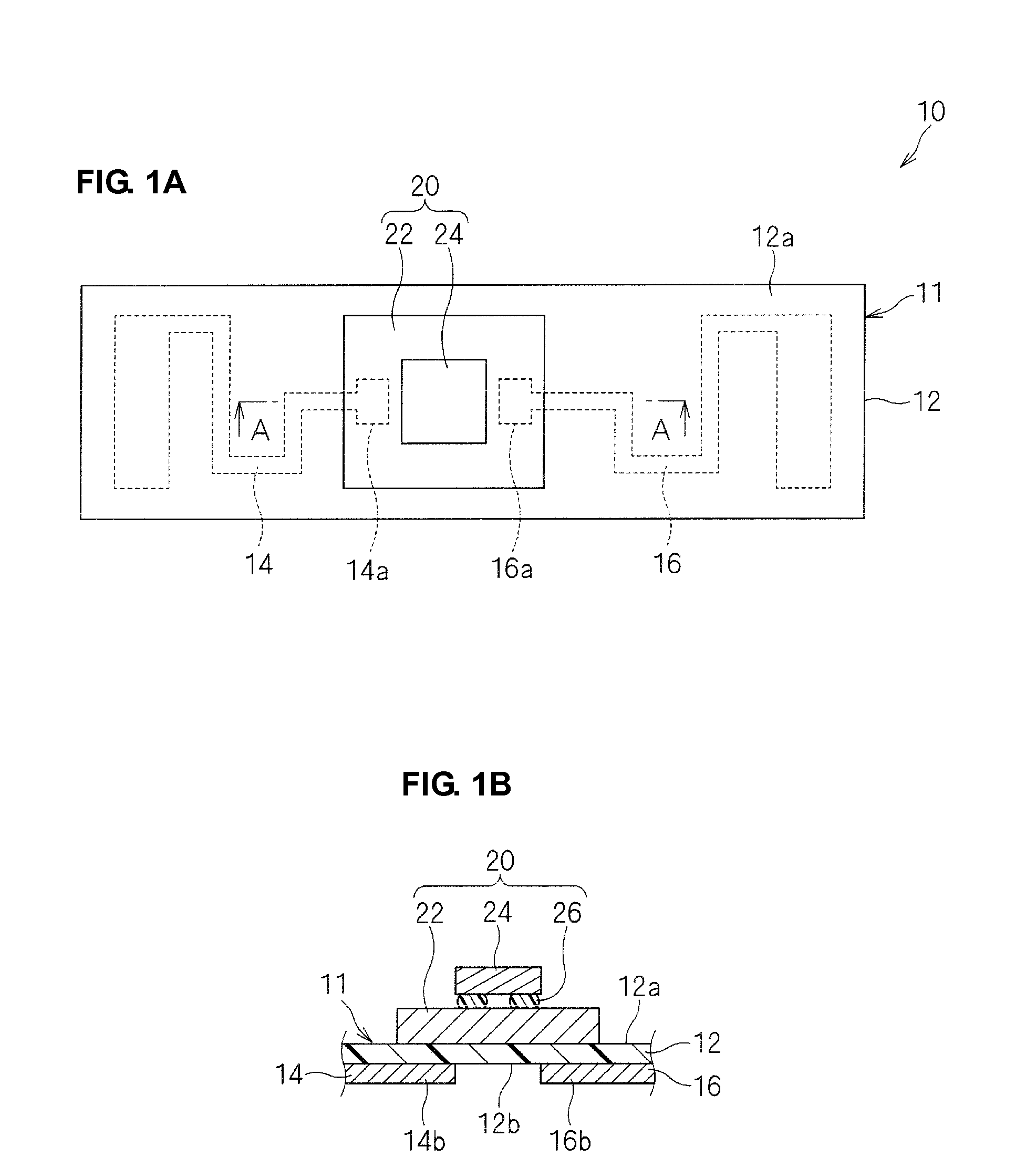
[0040]A wireless IC device according to a first preferred embodiment of the present invention will be described with reference to FIGS. 1A to 3. FIG. 1A is a plan view of a wireless IC device 10. FIG. 1B is a sectional view of a main portion, which is taken along the line A-A in FIG. 1A.
[0041]As illustrated in FIGS. 1A and 1B, the wireless IC device 10 includes an electromagnetic coupling module 20 including a feeding circuit substrate 22 and a wireless IC chip 24. The electromagnetic coupling module 20 is mounted on a top surface 12a, which is one of two main surfaces of a base 12 of a radiation plate 11. The wireless IC device 10 includes radiating electrode patterns 14 and 16 disposed on a bottom surface 12b of the base 12. Alternatively, the radiating electrode patterns may be disposed on the same surface on which the electromagnetic coupling module 20 is mounted.
[0042]The wireless IC device 10 is used by bonding the bottom surface 12b of the base 12 of the radiation plate 11 to...
second preferred embodiment
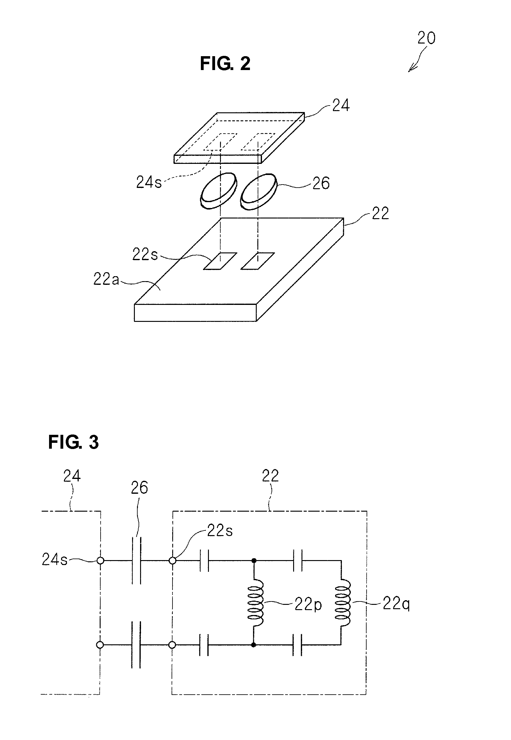
[0055]In a wireless IC device according to a second preferred embodiment of the present invention, an electromagnetic coupling module 20a is configured as illustrated in a sectional view of a main portion in FIG. 4.
[0056]That is, a dielectric body 26a is disposed on substantially the entire surface 22a of the feeding circuit substrate 22, which is on a side on which the wireless IC chip 24 is disposed. Since only a portion of the dielectric body 26a disposed between the mounting electrode 22s of the feeding circuit substrate 22 and the terminal electrode 24s of the wireless IC chip 24 establishes the capacity coupling, the dielectric body 26a may protrude from a portion that is required for capacity coupling.
[0057]The area of the dielectric body 26a is increased to substantially the size of the wireless IC chip 24, e.g., about 1000 μm2, or greater, and accordingly, the dielectric body 26a can be easily formed.
[0058]Since the dielectric body 26a is arranged in substantially the entir...
third preferred embodiment
[0059]In a wireless IC device according to a third preferred embodiment of the present invention, an electromagnetic coupling module 20b is configured as illustrated in a sectional view of a main portion in FIG. 5.
[0060]A dielectric body 26b preferably made of a mold resin, for example, is arranged along a periphery of the wireless IC chip 24. In a state in which the wireless IC chip 24 is covered with the dielectric body 26, the wireless IC chip 24 is mounted on the feeding circuit substrate 22. Since the wireless IC chip 24 is covered with the dielectric body 26b, entry of dirt, debris, water, moisture or other liquid, for example, into the wireless IC chip 24 is effectively prevented.
PUM
 Abstract
Description
Claims
Application Information