Partition wall in an aircraft

Active Publication Date: 2009-09-10
AIRBUS OPERATIONS GMBH
View PDF43 Cites 59 Cited by
  • Summary
  • Abstract
  • Description
  • Claims
  • Application Information

AI Technical Summary

Benefits of technology

[0027]The pluggability of the spars can, for example, be obtained by a connector-coupling system formed to their ends. In this arrangement the connector can, for example, be formed as a centring pin that engages a coupling that is formed as a centring aperture. Such a connector-coupling system is associated with an advantage in that the individual spars can be interconnected only in a manner predetermined by the connector-coupling system. Of course, a connection system is also imaginable in which the spars can be interconnected in any desired manner. For example, the spars can be produced in such a way that their ends only comprise centring apertures into which centring pins are inserted during installation. The spars can also be formed in any desired manner. Such forming can take place in a two-dimensional or in a three-dimensional manner.
[0028]In a further embodiment of the invention the spars are affixable among themselves by means of a tensioning mechanism. The tensioning mechanism makes it possible for the framework to be able to be brought from the folded state to the installed state and to be fixed. As a rule, for this purpose the ends of the spars are movable and connected to each other in a captive manner. Of course, it is possible that, when the frame

Problems solved by technology

However, processing requires considerable investment expenditure, for example for autoclaves, placement robots or refrigerated storage.
However, it has been shown that despite their production in the prepreg construction, partition walls are heavy.
Furthermore, considerable

Method used


Image

  • Partition wall in an aircraft
  • Partition wall in an aircraft
  • Partition wall in an aircraft

Examples


Embodiment Construction

[0123]It should be pointed out that identical components in the individual figures have the same reference characters.

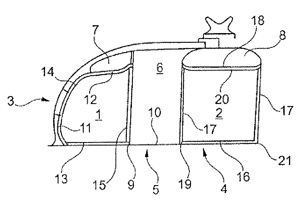
[0124]FIG. 1 shows a front view of a lateral partition wall 1 and a central partition wall 2 for partitioning seat rows in a passenger aircraft. The seat rows (not shown in the diagram) are installed on the one hand on the window side 3, and on the other hand in the centre region 4 of the aircraft. Between the seat rows there is an aisle 5 which extends in longitudinal direction of the aircraft, which aisle 5 leads from one passenger class to the next, and by way of which aisle 5 the passengers have access to their seats. Between the two partition walls 1 and 2 there is a curtain 6, which blocks the view from one passenger class to the other. In the upper region above the seat rows, so-called hatracks 7 and 8 are arranged, which accommodate the cabin baggage of passengers, with said hatracks 7 and 8 being closed off by hinged covers (not shown).

[0125]A first spar 13 ...


PUM


Abstract

The invention is based on a partition wall in an aircraft, wherein the partition wall comprises a support element and a tension-mounted material. According to the invention, the support element is composed of individually formed system components, and the tension-mounted material is supported by the support element such that an area-shaped partition wall is created in the aircraft.

Description

CROSS-REFERENCE TO RELATED APPLICATIONS[0001]This application claims the benefit of the filing date of U.S. Provisional Patent Application No. 61 / 067,309 filed Feb. 27, 2008, the disclosure of which is hereby incorporated herein by reference.BACKGROUND OF THE INVENTION[0002]The invention relates to the separation of regions in an aircraft. In particular, the invention relates to a partition wall in an aircraft, comprising a support element and a tension-mounted material, to a modular system for producing such a partition wall, to the use of the partition wall in an aircraft, and to a method for the production for the division of seat rows in an aircraft.[0003]In commercial aircraft, the seat rows for passengers are integrated in the fuselage such that the passengers are seated in the direction of flight, wherein the individual seat rows are arranged across the direction of flight at the window, and one behind another in the direction of the longitudinal axis of the aircraft. Seat ro...

Claims


Application Information

Patent Timeline
IPC IPC(8): B64C1/06B64C1/00G09F13/00
CPCB64D11/0023Y02T50/46G09F21/06Y02T50/40
Inventor NEUMANN, ANDREASMOSLER, MICHAELBREUER, MATTHIAS
Owner AIRBUS OPERATIONS GMBH
Why Eureka
Try Eureka