Evaporative humidifier

Inactive Publication Date: 2009-09-10
HITACHI PLANT TECH LTD
View PDF4 Cites 0 Cited by
  • Summary
  • Abstract
  • Description
  • Claims
  • Application Information

AI Technical Summary

Benefits of technology

[0011]As a first solution to solve the problem, the sensor sensitivity of the control valve of the humidifier may be lowered. Accordingly, the humidifier is not turned ON even if the humidity is low to a certain extent, so that the humidity value is prevented from fluctuating up and down due to the ON / OFF control.
[0013]On the other hand, as a second solution, a method of excessively heating the inlet air (outside air) more than normal first, humidifying the air, and subsequently, dehumidifying and cooling the humidified high-temperature air by the cooling coil, so as to control the air to have the target humidity may be employed as shown in a psychrometric chart in FIG. 9. According to the control method, there is such an advantage that accurate control is enabled since the control by cooling is easier than the control by heating and humidification.
[0015]The present invention has been made in view of such circumstances, and it is an object of the present invention to provide an evaporative humidifier capable of accurately performing humidity control without unnecessarily operating a humidifying device and without wasting energy.
[0017]In the present invention, a desired humidity is obtained by supplying water only to a humidifying module required for humidification. Air simply passes through a humidifying module to which water is not supplied. Accordingly, air obtained by mixing humidified air passing through the humidifying module which is wet with water being supplied thereto (wet zone) and non-humidified air passing through the humidifying module to which water is not supplied (dry zone) is blown out from an outlet of the evaporative humidifier. The mixture amount (mixture ratio) is controlled by the opening and closing of the valve, so that a desired humidity is obtained. Therefore, with the evaporative humidifier of the present invention, humidity control can be accurately performed without unnecessarily operating the humidifying device and without wasting energy.
[0024]As described above, according to the evaporative humidifier of the present invention, humidity control can be accurately performed without unnecessarily operating the humidifier and without wasting energy.

Problems solved by technology

However, the method of controlling a humidification amount shown in FIG. 7 has such a problem that when a humidifier to be attached to an outside air conditioner is assumed, the humidifier is very difficult to control in the intermediate season such as spring or autumn in which the humidity of air around the inlet is close to the target humidity since the evaporative humidifier 1 has only ON / OFF control.
However, in the case of the first solution, once the humidifier is turned ON, humidification is performed in substantial amounts.
Thus, the control cannot be considered as appropriate control.

Method used


Image

  • Evaporative humidifier
  • Evaporative humidifier
  • Evaporative humidifier

Examples


first embodiment

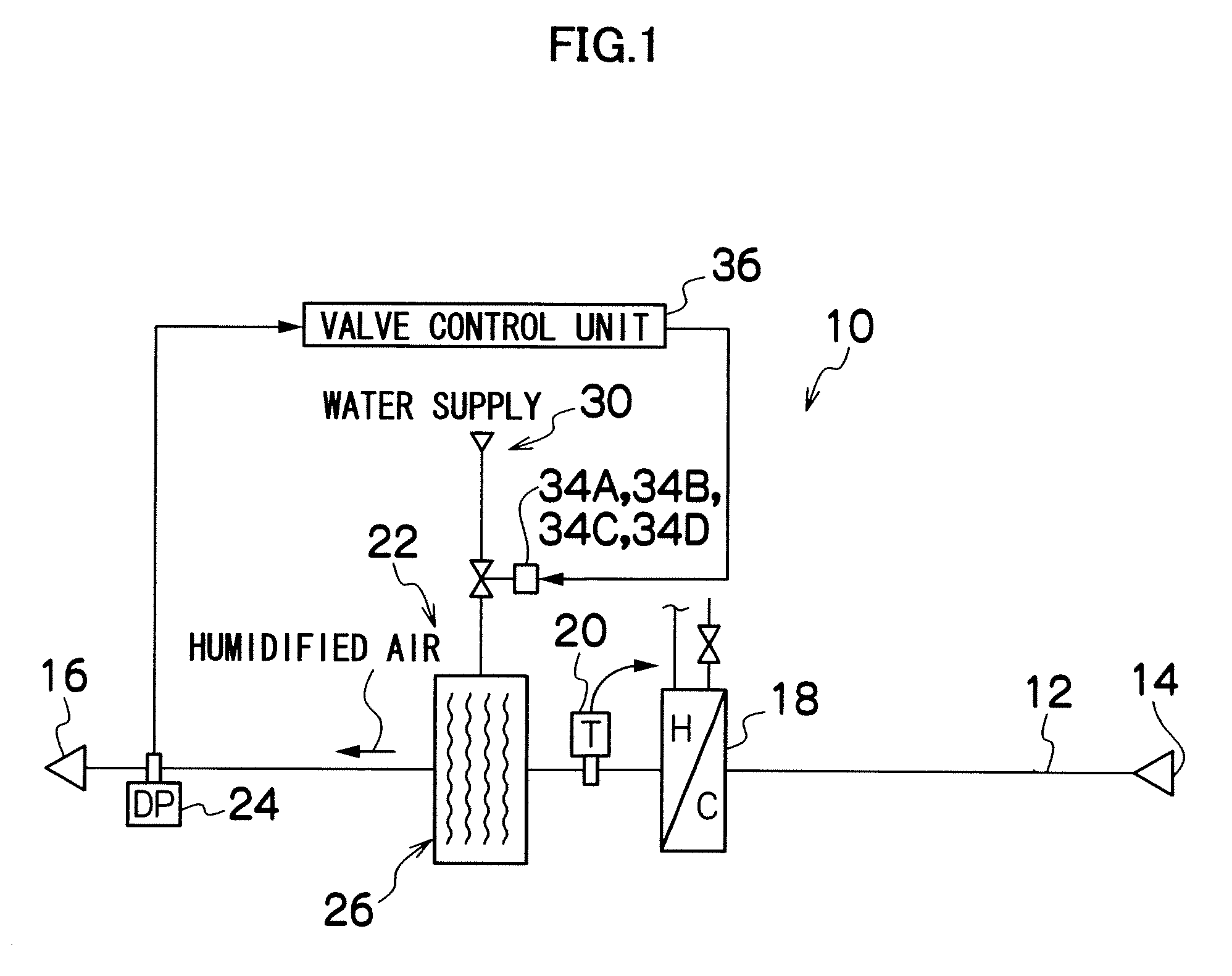
[0037]A thermometer 20 is provided on the downstream side of the humidification flow path 12 from the cooling / heating coil 18. The temperature of air passing through the cooling / heating coil 18 is measured by the thermometer 20. The amount or temperature of the cooling / heating medium to be supplied to the cooling / heating coil 18 is feedback-controlled by an unillustrated control device based on the measured air temperature. A humidifying device 22 is provided on the downstream side of the humidification flow path 12 from the thermometer 20. Also, a dew-point meter (dew-point detecting device) 24 is provided on the downstream side of the humidification flow path 12 from the humidifying device 22.

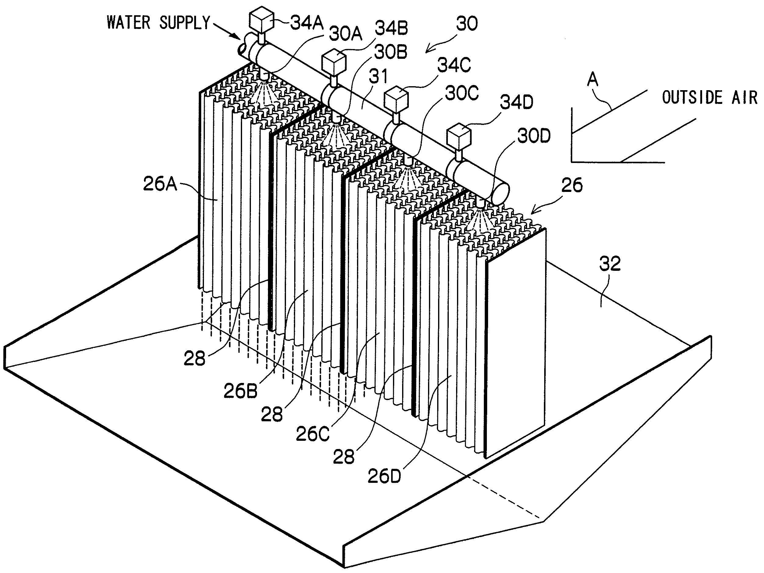
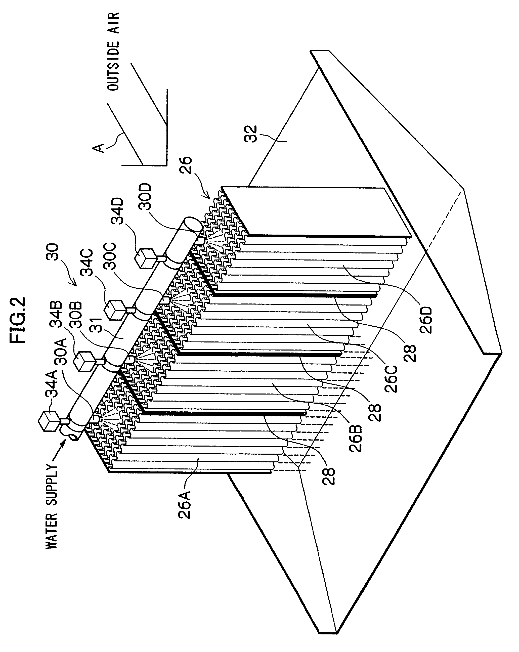
[0038]A humidifying element 26 which constitutes the humidifying device 22 according to the first embodiment is disposed in a direction perpendicular to a flow direction A of the introduced outside air as shown in FIG. 2. The humidifying element 26 is formed into a rectangular shape in secti...

second embodiment

[0050]Therefore, when the water supply electromagnetic valve 134A is opened, water is injected from the injection holes formed in the respective water supply pipes 133 between the water supply electromagnetic valve 134A and the respective water supply electromagnetic valves 134B, and water is thereby supplied to the humidifying module 126A of the humidifying element 122. When the water supply electromagnetic valve 134A and the respective water supply electromagnetic valves 134B are opened, water is injected from the injection holes formed in the respective water supply pipes 133 between the water supply electromagnetic valve 134A and the respective water supply electromagnetic valves 134C, and water is thereby supplied to the humidifying modules 126A and 126B of the humidifying element 122. Furthermore, when the water supply electromagnetic valve 134A, the respective water supply electromagnetic valves 134B and the respective water supply electromagnetic valves 134C are opened, wate...

third embodiment

[0053]That is, by controlling the opening and closing of the water supply electromagnetic valves 234A to 234F, the humidifying module to which water is to be supplied is selected from the humidifying modules 226A to 226F. Accordingly, the humidifying module which gets wet with water (wet zone) and the humidifying module to which water is not supplied (dry zone) are formed in one humidifying element 226. The opening and closing of the water supply electromagnetic valves 234A to 234F is controlled by a valve control unit (not shown in FIG. 4) in a similar manner to FIG. 1. The valve control unit controls the opening and closing of the water supply electromagnetic valves 234A to 234F based on the dew point detected by the dew-point meter 24 such that a desired humidity is obtained in a similar manner to FIG. 1. In the humidifying device 222 water is also supplied only to the humidifying module required for humidification in the humidifying element 226, so as to obtain a desired humidi...


PUM

PropertyMeasurementUnit
Temperatureaaaaaaaaaa
Thicknessaaaaaaaaaa
Humidityaaaaaaaaaa

Abstract

In the evaporative humidifier of the present invention, a desired humidity is obtained by supplying water only to a humidifying module required for humidification. Air simply passes through a humidifying module to which water is not supplied. Accordingly, air obtained by mixing humidified air passing through the humidifying module which is wet with water being supplied thereto (wet zone) and non-humidified air passing through the humidifying module to which water is not supplied (dry zone) is blown out from an outlet of the evaporative humidifier. The mixture amount (mixture ratio) is controlled by the opening and closing of the valve, so that a desired humidity is obtained. Therefore, with the evaporative humidifier of the present invention, humidity control can be accurately performed without unnecessarily operating the humidifying device and without wasting energy.

Description

BACKGROUND OF THE INVENTION[0001]1. Field of the Invention[0002]The present invention relates to an evaporative humidifier, and more particularly, to an evaporative humidifier which is installed to control temperature and humidity in a precision equipment factory such as a clean room.[0003]2. Description of the Related Art[0004]In the precision equipment factory such as a clean room, it is necessary to keep the temperature and humidity constant. An evaporative humidifier as disclosed in Japanese Patent Application Laid-Open No. 2001-317795 is known as a humidifying apparatus for performing temperature and humidity control in such a room.[0005]The evaporative humidifier includes a heating coil, an evaporative humidifier, a cooling coil, a fan, a dry-bulb temperature sensor, and a dew-point temperature sensor, which are disposed from an air inlet side to an air outlet side of an air flow path formed by a housing.[0006]The evaporative humidifier is composed of a humidifying module in w...

Claims


Application Information

Patent Timeline
IPC IPC(8): B01F3/04
CPCF24F6/04F24F3/14
Inventor YOKOYAMA, AKIRASUZUKI, KOJIKAWASAKI, KOSEI
Owner HITACHI PLANT TECH LTD
Why Eureka
Try Eureka