Dc-dc converter

a converter and direct current technology, applied in the direction of dc-dc conversion, power conversion systems, instruments, etc., can solve the problems of long time to converge on the required voltage, dc-dc converters can fail to generate the required output voltage, and malfunctions, etc., to achieve reliable pulse-width modulation and stable output voltage

Inactive Publication Date: 2009-09-10
RICOH ELECTRONIC DEVICES CO LTD
View PDF4 Cites 11 Cited by
  • Summary
  • Abstract
  • Description
  • Claims
  • Application Information

AI Technical Summary

Benefits of technology

[0029]Therefore, the present invention can provide a DC-DC converter that can perform reliable pulse-width modulation to output a stable output voltage by controlling the modulation of the pulse widths using the linear part of the triangular wave.

Problems solved by technology

If the power supply becomes unstable, operations of the load become unstable, and accordingly, malfunction will occur.
Due to the non-linearity of the slope, the pulse width of a subsequent duty control signal from the PWM comparison circuit 212 fluctuates, which is a problem.
As described above, since the output triangle slope has such a non-linear shape, it can take a longer time to converge on a required voltage, and at worst, the DC-DC converter can fail to generate the required output voltage.
However, although the above-mentioned approach considers the case in which the output voltage drops significantly, it does not consider the case in which the triangular wave is not linear.
Thus, a required pulse width signal cannot be generated in the case in which an error output signal is lower when the triangular wave is not linear.

Method used


Image

  • Dc-dc converter
  • Dc-dc converter
  • Dc-dc converter

Examples


first embodiment

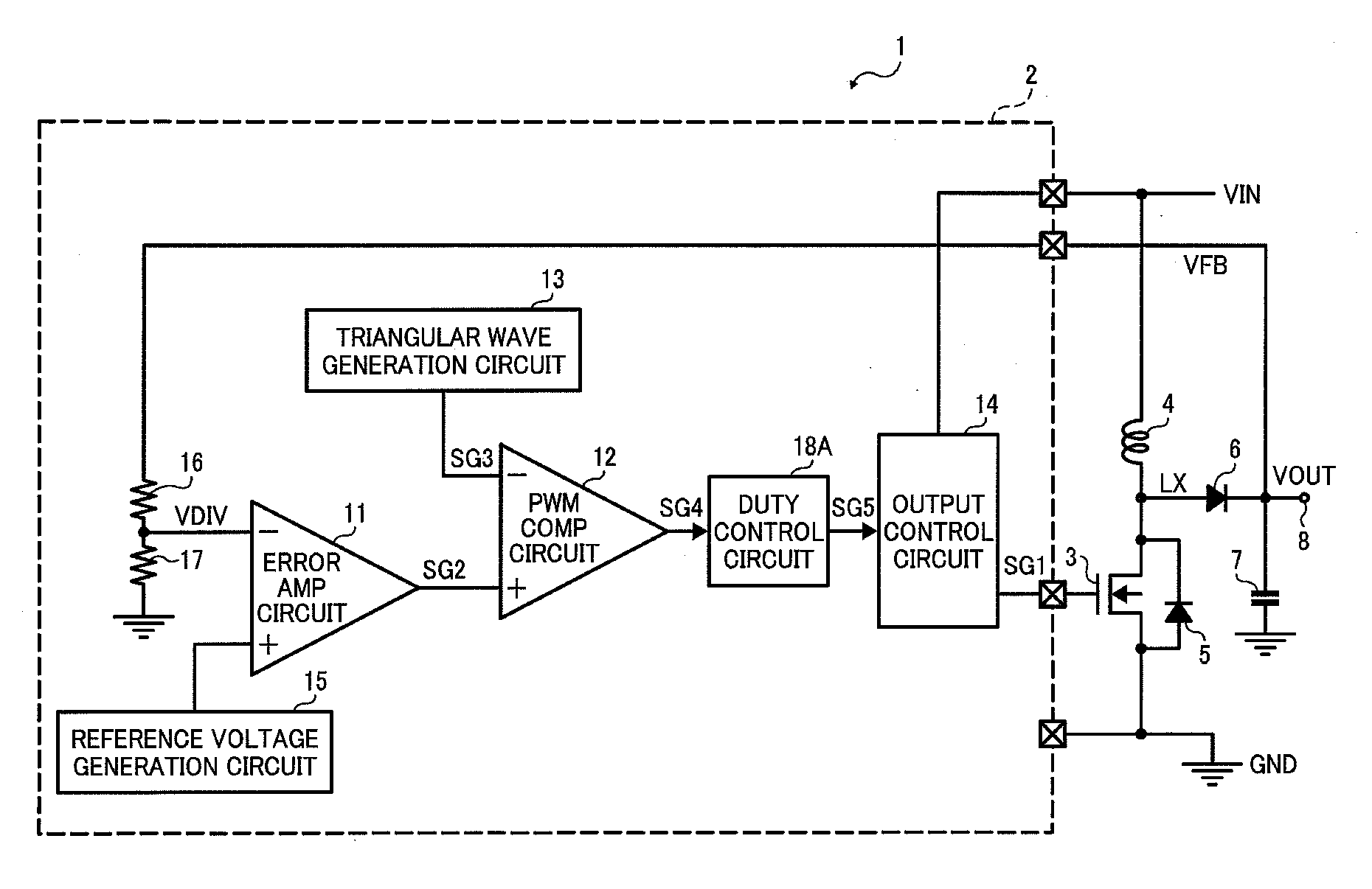
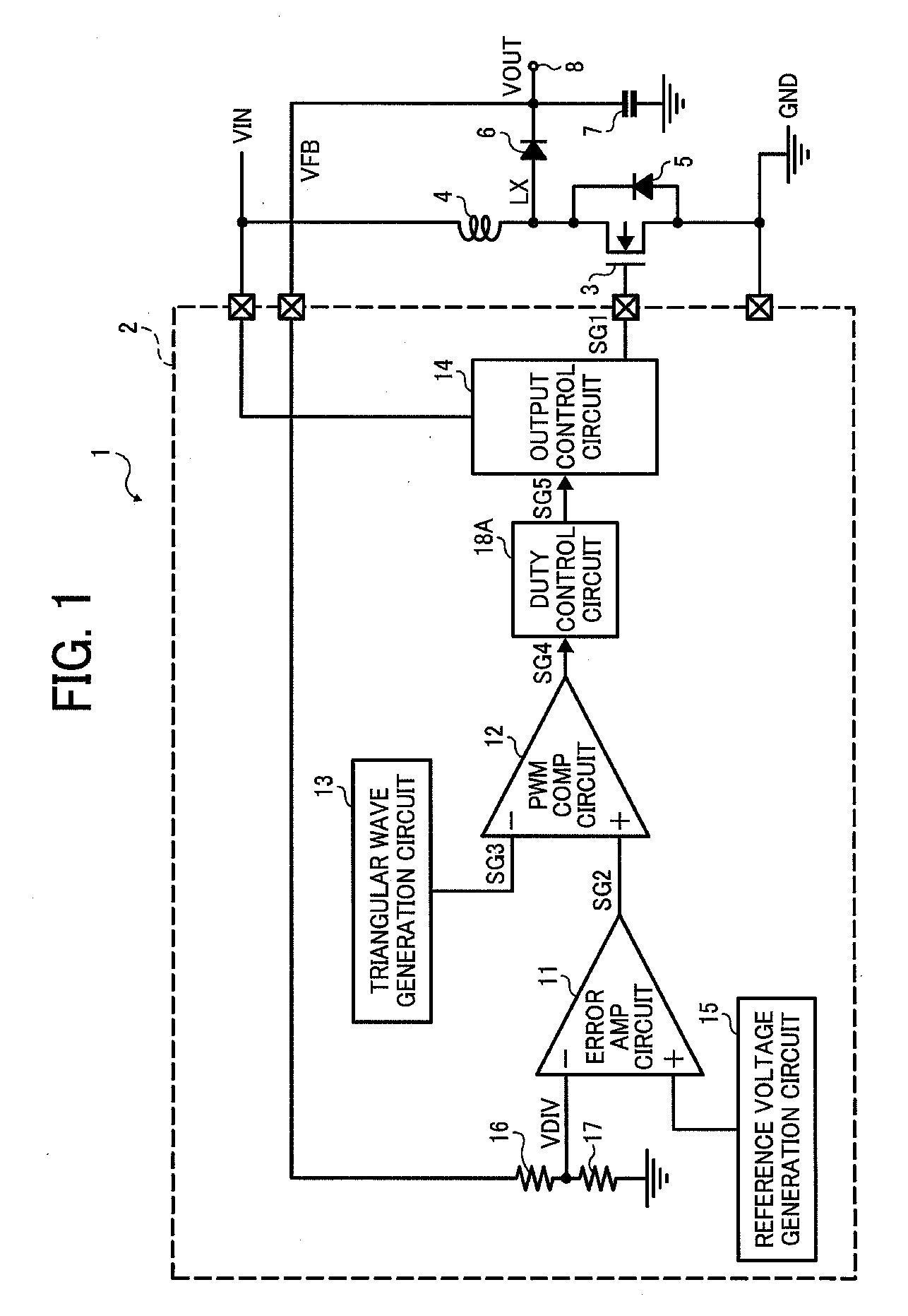
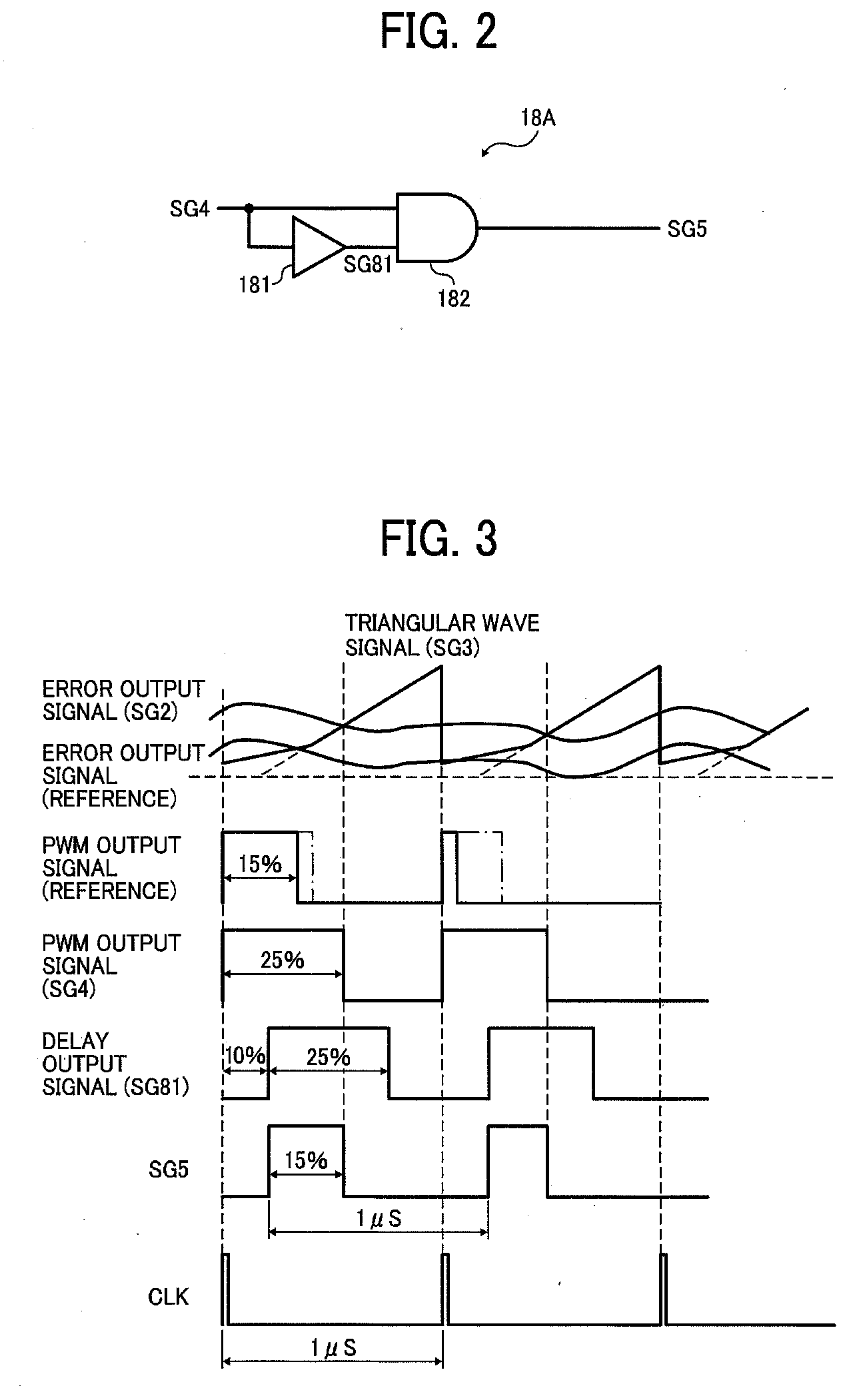
[0081]In the first embodiment, the pulse-width control circuit 18A reduces the duty ratio of the duty control signal SG4 by 10%.

second embodiment

[0082]By contrast, in the second embodiment, the pulse-width control circuit 18B is designed to control the duty control signal SG4 so that it raises the duty ratio by 10% and outputs the signal SG5 whose pulse width is controlled. The pulse-width control circuit 18B outputs the signal SG5 whose pulse width is increased by 10% from that of the duty control signal SG4, and the signal SG5 controls the output control circuit 14. As a result, the level of the error output signal SG2 becomes lower by 10% than that of the signal LX.

[0083]Therefore, in the present embodiment, when the duty ratio of the signal LX is set to 95%, the period during which the signal level of the triangular wave signal SG3 is higher than that of the error output signal SG2 is 85% of 1 cycle. Thus, the level of the error output signal SG2 in the DC-DC converter 1 that includes the pulse-width control circuit 18 raising the duty ratio 10% is reduced by 10% compared to the error output signal SG2 in the DC-DC conve...

third embodiment

[0098]In the third embodiment, the pulse-width control circuit 18C includes a first circuit, a second circuit, and a selector 185. The first circuit consists of a delay circuit 181 and an AND circuit 182, and outputs the signal SG5 whose pulse width is reduced by a predetermined or given amount. The second circuit consists of the delay circuit 181 and an OR circuit 183, and outputs the signal SG5 whose pulse width is raised by a predetermined or given amount.

[0099]The selector 185 selects either the first circuit or the second circuit and outputs the signal SG5 that is output from the selected circuit. The selector 185 is controlled based on the input voltage and the output voltage.

[0100]Therefore, in the present embodiment, the input voltage and the output voltage is detected by the detection circuits 21 and 22, and signals from these detection circuits 21 and 22 are provided to the controller 20.

[0101]Based on the relation between the input voltage and the output voltage, the cont...


PUM


Abstract

A DC-DC converter includes an error amplifying circuit to output an error signal by amplifying differences between a reference voltage and a feedback voltage for an output voltage generated by switching an output transistor between on and off, a triangular wave generation circuit to generate a triangular wave, a PWM comparison circuit to compares the triangular wave with the error signal and output a duty control signal having a duty ratio based on the comparison, a pulse width control circuit to control a pulse width of the duty control signal output from the PWM comparison circuit, and a drive circuit to drive the output transistor according to a signal output from the pulse width control circuit.

Description

CROSS-REFERENCE TO RELATED APPLICATIONS[0001]This patent specification claims priority from Japanese Patent Application No. 2008-060005, filed on Mar. 10, 2008 in the Japan Patent Office, the entire contents of which are hereby incorporated by reference herein.BACKGROUND OF THE INVENTION[0002]1. Field of the Invention[0003]The present invention relates to a DC-DC (direct current to direct-current) converter that controls operations of a switching element based on an output voltage and maintains the output voltage within a predetermined range.[0004]More particularly, the present invention relates to a DC-DC converter that supplies operational power to various types of semiconductor integrated circuit (IC) devices, such as a central processing unit (CPU) and a memory (RAM, ROM, etc.), mounted on any of various types of electronic apparatuses. For example, applications thereof can be a power source for digital home appliance such as DVD players using both blue- and red-type LD, and DVD...

Claims


Application Information

Patent Timeline
Patent Type & Authority Applications(United States)
IPC IPC(8): G05F3/04
CPCH02M3/156H02M3/155H03K7/08
Inventor YAMADA, SHINICHIRO
Owner RICOH ELECTRONIC DEVICES CO LTD
Why Eureka
Try Eureka