Signal modulation circuit
a signal modulation circuit and signal technology, applied in the field of signal modulation circuits, can solve problems such as noise shaping, and achieve the effect of reliably modulating and reducing the influence of distortion/noise components in the delay devi
- Summary
- Abstract
- Description
- Claims
- Application Information
AI Technical Summary
Benefits of technology
Problems solved by technology
Method used
Image
Examples
first embodiment
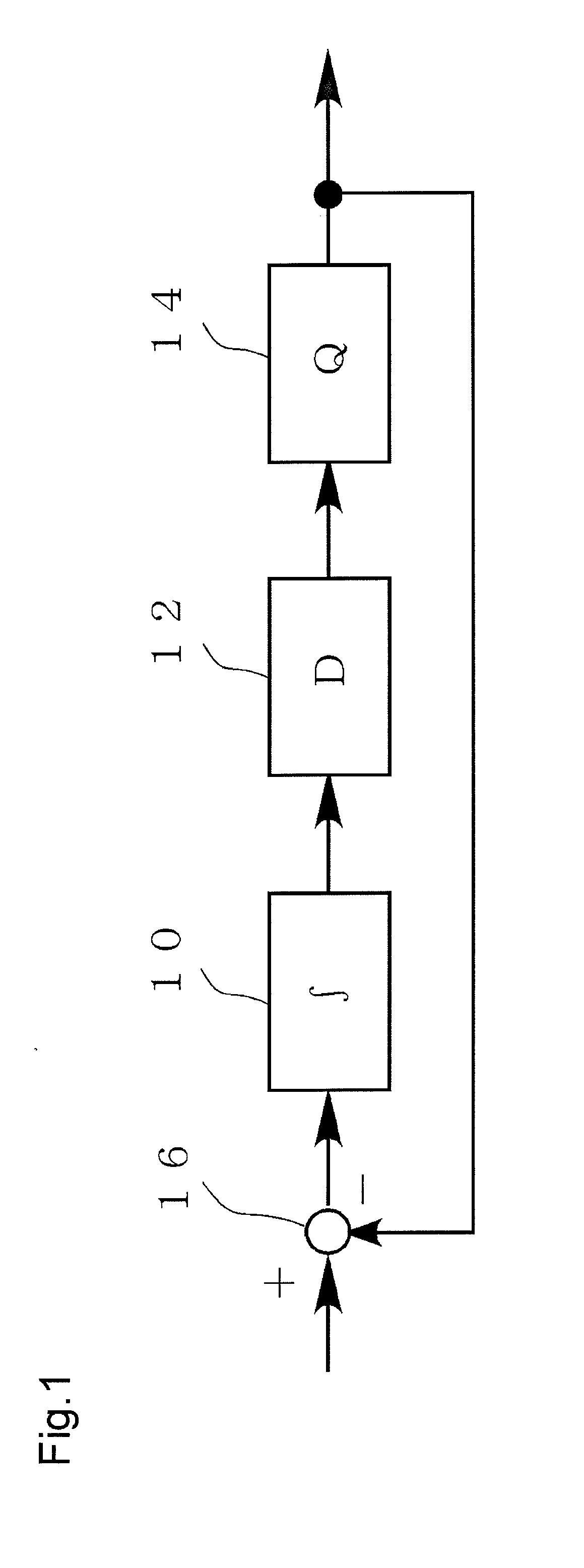
[0039]FIG. 1 illustrates a basic configuration of a signal modulation circuit according to the first embodiment. The signal modulation circuit according to this embodiment performs delta sigma modulation on an input signal, and includes a subtracter 16, an integrator 10, a delay device 12, and a quantizer 14.
[0040]The circuit shown in FIG. 1 is compared with a circuit shown in FIG. 17. In the circuit according to this embodiment, the delay device 12 is not present on a feedback path, but is provided at a front stage of the quantizer 14, that is, between the integrator 10 and the quantizer 14. Therefore, in the circuit according to this embodiment, an output state can be corrected in real time.
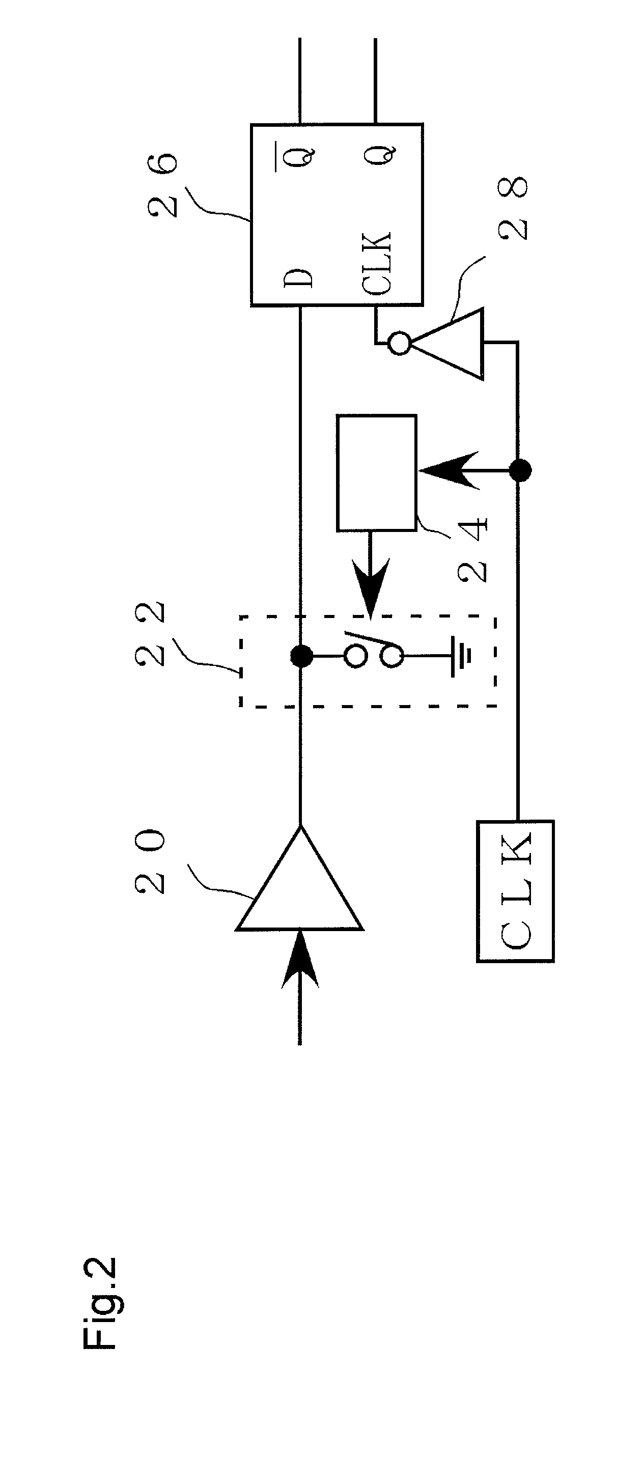
[0041]The delay device 12 according to this embodiment has a function for not only delaying an input signal but also inserting a zero level into an input signal, and this realizes more reliable pulse density modulation. Any circuit for inserting the zero level into an input signal is used, but ...
second embodiment
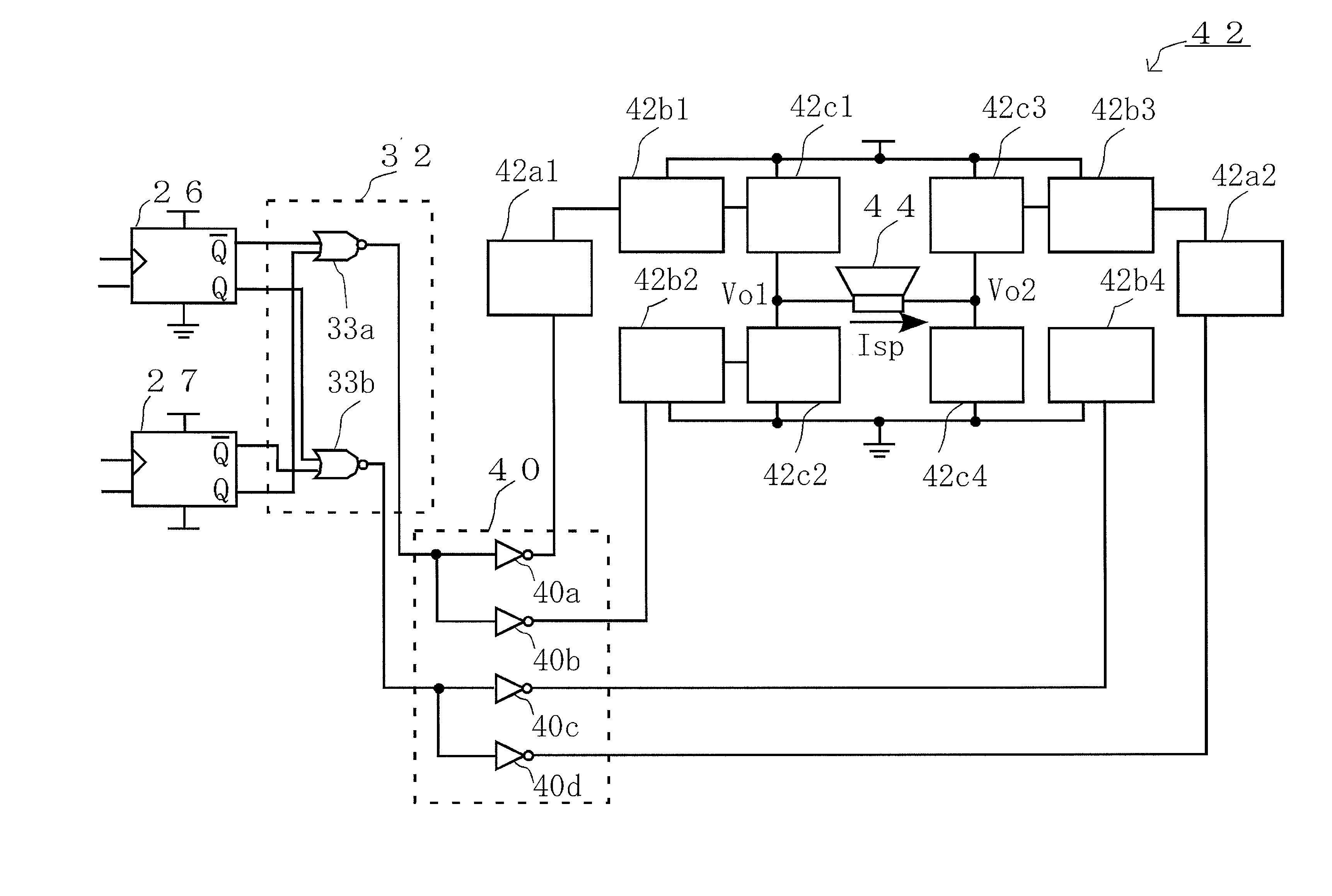
[0059]The spread of portable devices and the demand for energy saving in recent years require further promotion of efficiency of class-D amplifiers. Since general class-D amplifiers express a level using an average value of two signals of a positive voltage and a negative voltage, as to a non-signal state that is a zero voltage, a positive voltage and a negative voltage are expressed by a duty of 50%. That is, in the class-D amplifiers realized by binary signals, switching cross occurs also at the non-signal time, and thus the improvement in the switching cross is demanded. However, it is difficult for a binary signal to generate a state where switching is not performed at the non-signal state.
[0060]The second embodiment, therefore, describes a configuration in which, while the configuration in the first embodiment is being used, a ternary PDM signal of +1, 0, and −1 are generated so that the state where the switching is not performed at the non-signal time is generated.
[0061]FIG. 6...
third embodiment
[0073]In the second embodiment, a ternary PDM signal of +1, 0, and −1 is generated to be output, and the bias generating circuit 30 and the bias generating circuit 31 apply a bias voltage so that the switching at the non-signal time is suppressed. However, since a bias voltage is applied not only at the non-signal time but also at a signal generated time, distortion may occur.
[0074]The third embodiment, therefore, describes a circuit configuration in which the switching at the non-signal time is suppressed, and distortion at the signal generated time can be reduced.
[0075]FIG. 10 illustrates a circuit configuration according to this embodiment. In addition to the circuit configuration shown in FIG. 6, a signal detector 34 is further provided. In FIG. 10, in view of the matching of the configuration between the bias generating circuit 30 and the bias generating circuit 31, the configuration is illustrated for both the circuits.
[0076]The signal detector 34 detects presence and absence ...
PUM
 Abstract
Description
Claims
Application Information
 - R&D
- Intellectual Property
- Life Sciences
- Materials
- Tech Scout
- Unparalleled Data Quality
- Higher Quality Content
- 60% Fewer Hallucinations
Browse by: Latest US Patents, China's latest patents, Technical Efficacy Thesaurus, Application Domain, Technology Topic, Popular Technical Reports.
© 2025 PatSnap. All rights reserved.Legal|Privacy policy|Modern Slavery Act Transparency Statement|Sitemap|About US| Contact US: help@patsnap.com


