Ladderway system for underground raises

a ladderway and underground technology, applied in the direction of ladders, mining structures, building scaffolds, etc., can solve the problems of difficult and expensive maintenance, ladderway constant exposure, and difficult to ascertain

Active Publication Date: 2009-09-17
BORTANA
View PDF8 Cites 10 Cited by
  • Summary
  • Abstract
  • Description
  • Claims
  • Application Information

AI Technical Summary

Benefits of technology

[0006]According to the present invention there is provided a ladderway system for an underground raise, the system comprising:an elongate tube adapted to generally conform to the shape of the raise;a ladder adapted to be mechanically coupled to an interior of said tube and extending substantially the full length of the tube; anda mounting means for mounting the ladder and the tube to a wall of the raise, wherein the tube acts as a liner for the raise to protect a person on the ladder.

Problems solved by technology

Apart from the fact that such steel ladderways are heavy and expensive to manufacture and install, they are also difficult and expensive to maintain.
The ladderway is constantly exposed to groundwater and seepage which contribute to corrosion, particularly in highly saline groundwater conditions.
It is difficult to ascertain to what extent the steel has corroded over time and the safety of the ladderway is compromised.
Furthermore, the steel mesh cage does not provide adequate protection for miners from rock falls.

Method used


Image

  • Ladderway system for underground raises
  • Ladderway system for underground raises
  • Ladderway system for underground raises

Examples


first embodiment

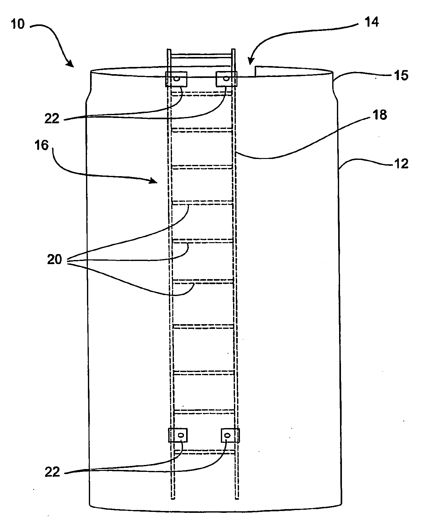
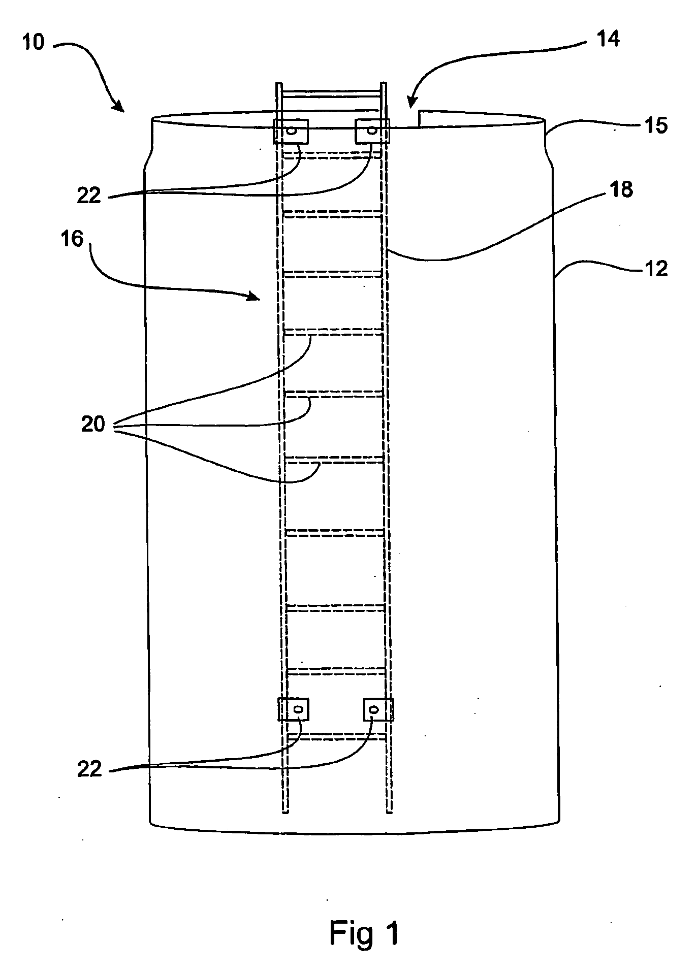
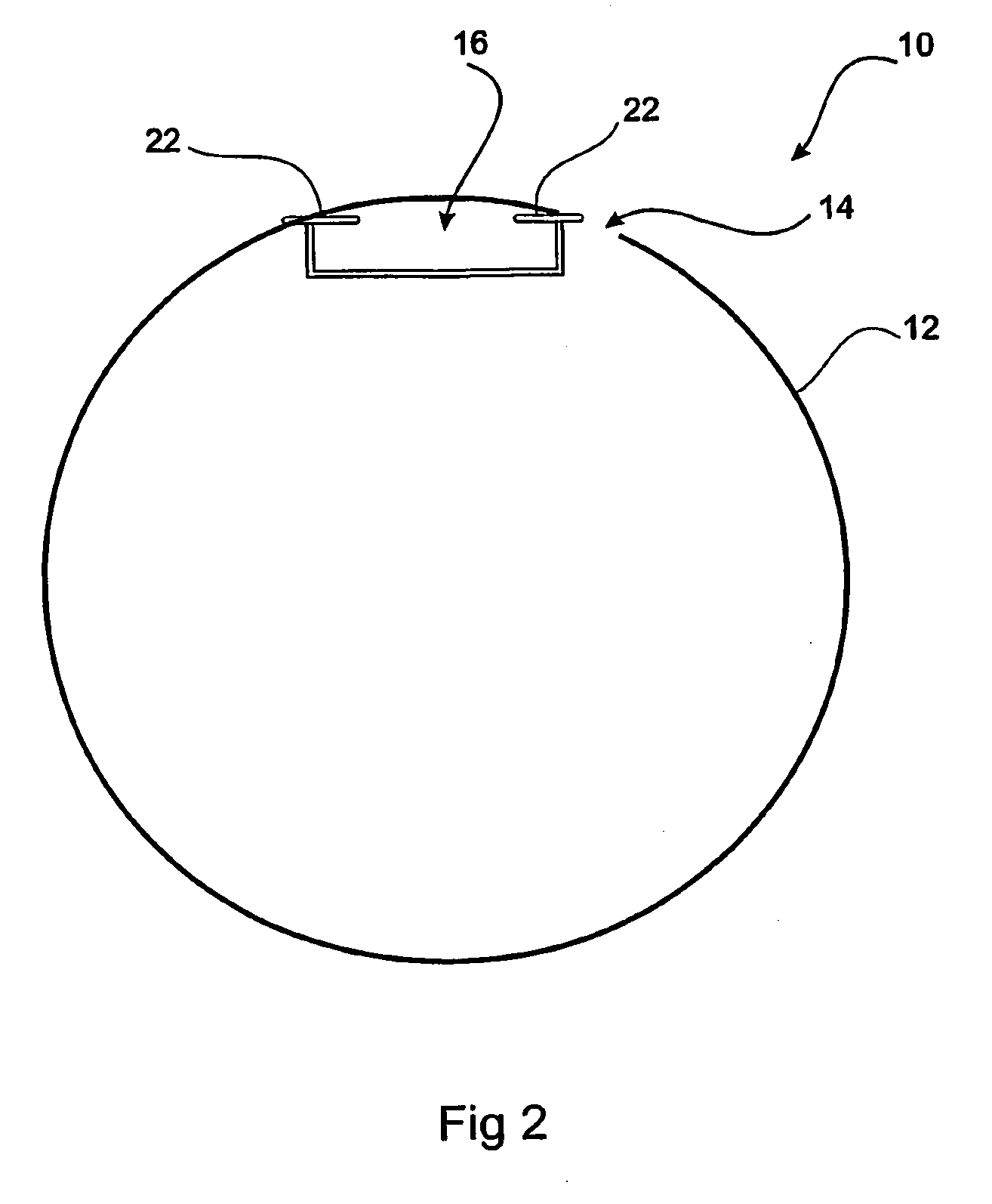
[0020]a ladderway system 10 for an underground raise (not shown), as illustrated in FIGS. 1 and 2, comprises an elongate tube 12 adapted to generally conform to the shape of the rise. In this embodiment the tube 12 is of circular cross-section to generally conform to the shape of a round bored raise approximately 1 m in diameter. However, it will be understood that the tube 12 may be of any desired cross-sectional shape. The tube 12 is formed with a longitudinal slit 14 along its entire length, as can be seen most clearly in FIG. 2, whereby the diameter of the tube 12 can be adjusted to generally conform to the shape of the raise. The ladderway system 10 further comprises a ladder 16 adapted to be mechanically coupled to an interior of the tube 12.

[0021]Preferably the tube 12 is made of resilient plastics material. The tube is typically installed in a relaxed state, with its diameter reduced so as to be more easily received in the rise, and when the ladder 16 is installed the tube 1...

second embodiment

[0033]a ladderway system 40 for an underground raise will now be described with reference to FIGS. 4 to 6. The ladderway system 40 comprises an elongate tube 42 adapted to generally conform to the shape of the rise. In this embodiment the tube 42 is also of circular cross-section to generally conform to the shape of a round bored raise. However, it will be understood that the tube 42 may also be of any desired cross-sectional shape. As in the previous embodiment, the tube 42 is formed with a longitudinal slit 44 along its entire length, as can be seen most clearly in FIGS. 4 and 5, whereby the diameter of the tube 12 can be adjusted to generally conform to the shape of the raise. However, in this embodiment the slit 44 is of larger width so that even when the tube 42 is installed a significant gap remains between the edges of the two sides of the slit 44.

[0034]The ladderway system 40 further comprises a ladder 46 adapted to be mechanically coupled to an interior of the tube 42. In t...


PUM

PropertyMeasurementUnit
angleaaaaaaaaaa
anglesaaaaaaaaaa
anglesaaaaaaaaaa

Abstract

A ladderway system for an underground raise includes an elongate tube adapted to generally conform to the shape of the raise. The tube is of circular cross-section to generally conform to the shape of a round bored raise. The tube is formed with a longitudinal slit along its entire length, whereby the diameter of the tube can be adjusted to generally conform to the shape of the raise. The ladderway system further includes a ladder adapted to be mechanically coupled to an interior of the tube. The tube manufactured of a sufficiently rigid and strong plastics material, such as polyurethane, so that it acts as a surface membrane or liner within the raise.

Description

FIELD OF THE INVENTION[0001]The present invention relates to a ladderway system for underground raises and relates particularly, though not exclusively, to a ladderway system for underground mine development.BACKGROUND TO THE INVENTION[0002]Underground mines are required to provide ventilations raises, which may also serve as emergency escape raises through which underground miners can escape to the surface in the event of an emergency. For this purpose it is common for such underground escape raises to be provided with a ladderway to permit miners to climb up out of the mine. Conventional ladderways are typically in the form of a prefabricated steel ladder surrounded with a steel mesh caging to provide a measure of protection for the miners as they climb the ladder.[0003]Apart from the fact that such steel ladderways are heavy and expensive to manufacture and install, they are also difficult and expensive to maintain. The ladderway is constantly exposed to groundwater and seepage w...

Claims


Application Information

Patent Timeline
Patent Type & Authority Applications(United States)
IPC IPC(8): E06C9/02B23P11/00
CPCE06C9/02Y10T29/49826E21F11/00
Inventor DURKIN, STEVEN PETER
Owner BORTANA
Why Eureka
Try Eureka