Inductive power supply system with multiple coil primary

a power supply system and coil primary technology, applied in the field of inductive coupling, can solve the problems of large differences in power requirements and limited success of conventional systems, and achieve the effects of low, medium and high power and energy saving

Active Publication Date: 2009-09-17
PHILIPS IP VENTURES BV
View PDF39 Cites 520 Cited by
  • Summary
  • Abstract
  • Description
  • Claims
  • Application Information

AI Technical Summary

Benefits of technology

[0008]One benefit of an inductive power supply having a coil assembly with multiple coils is that a single hot spot may deliver low, medium and high power to a remote device. This reduces the need to have an inductive power supply that powers low power devices, a separate inductive power supply to power medium power devices and a separate inductive power supply that power high power devices. Further, energy savings may result because higher power devices may use a lower power coil during lower power consumption periods. Additionally, lower power devices may draw power from a higher power coil in order to gain spatial freedom.

Problems solved by technology

Conventional systems have met with limited success as a result of practical limitations on pre-existing inductive technology.
These problems are complicated by the fact that different remote devices may require vastly different amounts of power.

Method used


Image

  • Inductive power supply system with multiple coil primary
  • Inductive power supply system with multiple coil primary
  • Inductive power supply system with multiple coil primary

Examples


Embodiment Construction

[0025]I. Overview

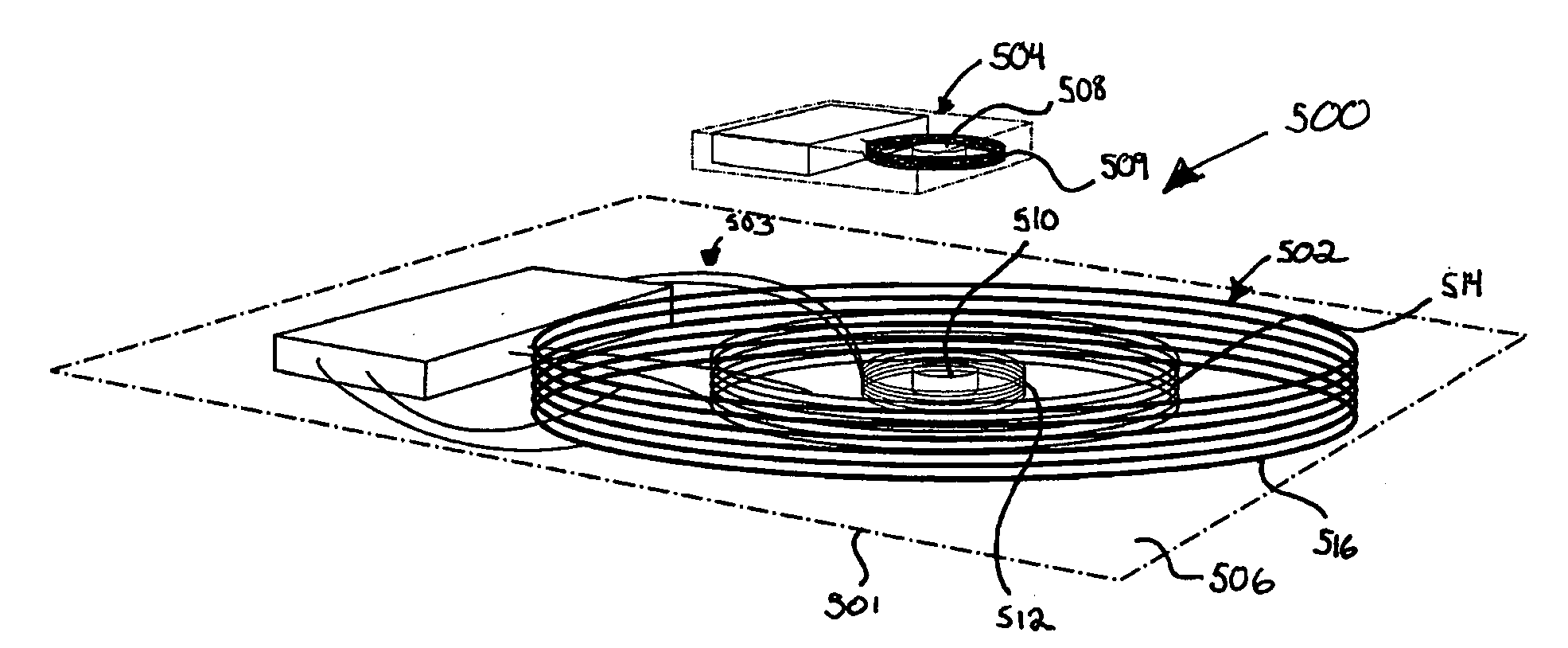
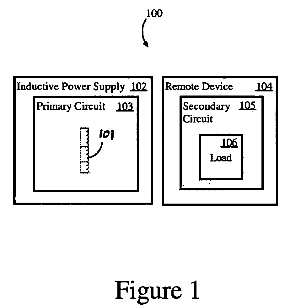
[0026]In an exemplary embodiment of the inductive power supply system of the present invention depicted in FIG. 1 and designated 100, the inductive power supply system includes an inductive power supply 102 and a remote device 104. The inductive power supply includes a primary circuit 103 having a primary coil assembly 101 capable of generating multiple ranges of power. The remote device 104 includes a secondary circuit 105 having a load 106. The secondary circuit 105 of the remote device includes power demand information that may include a power class. The power demand information may be transmitted to the inductive power supply 102 in order to facilitate power transfer at an appropriate range of power. In response to the power demand information, the primary circuit 103 selects an appropriate coil of the primary coil assembly 101 over which to transfer power to the remote device 104. In one embodiment, the coil is selected at least in part as a function of the pow...


PUM

PropertyMeasurementUnit
poweraaaaaaaaaa
poweraaaaaaaaaa
poweraaaaaaaaaa

Abstract

An inductive power supply including multiple tank circuits and a controller for selecting at least one of the tank circuits in order to wirelessly transfer power based on received power demand information. In addition, a magnet may be used to align multiple remote devices with the inductive power supply. In one embodiment, different communication systems are employed depending on which coil is being used to transfer wireless power.

Description

[0001]This application claims the benefit of U.S. Provisional Application No. 61 / 036,459 filed Mar. 13, 2008.BACKGROUND OF THE INVENTION[0002]The present invention relates to inductive coupling and more particularly to systems and methods for providing multiple ranges of inductive power.[0003]Systems for providing wireless power using the principles of electromagnetic inductive have been available for many years. Conventional systems have met with limited success as a result of practical limitations on pre-existing inductive technology. For example, to provide reasonably efficient operation, conventional inductive systems typically require close and precise alignment between the primary coil and the secondary coil, as well as a high degree of coordinated tuning between the electronics in the inductive power supply and the electronics in the remote device. These problems are complicated by the fact that different remote devices may require vastly different amounts of power. For examp...

Claims


Application Information

Patent Timeline
Patent Type & Authority Applications(United States)
IPC IPC(8): H01F38/00
CPCH01F38/14H04B5/0037H02J5/005H01F27/2871H04B5/0062H04B5/0075H04B5/0093H02J50/12H02J50/70H02J50/005H02J50/40H02J50/10
Inventor BAARMAN, DAVID W.MOLLEMA, SCOTT A.SCHWANNECKE, JOSHUA K.
Owner PHILIPS IP VENTURES BV
Why Eureka
Try Eureka