
Display device and a televsion receiver having the same

Active Publication Date: 2009-09-17
SHARP KK
View PDF6 Cites 15 Cited by
  • Summary
  • Abstract
  • Description
  • Claims
  • Application Information

AI Technical Summary

Benefits of technology

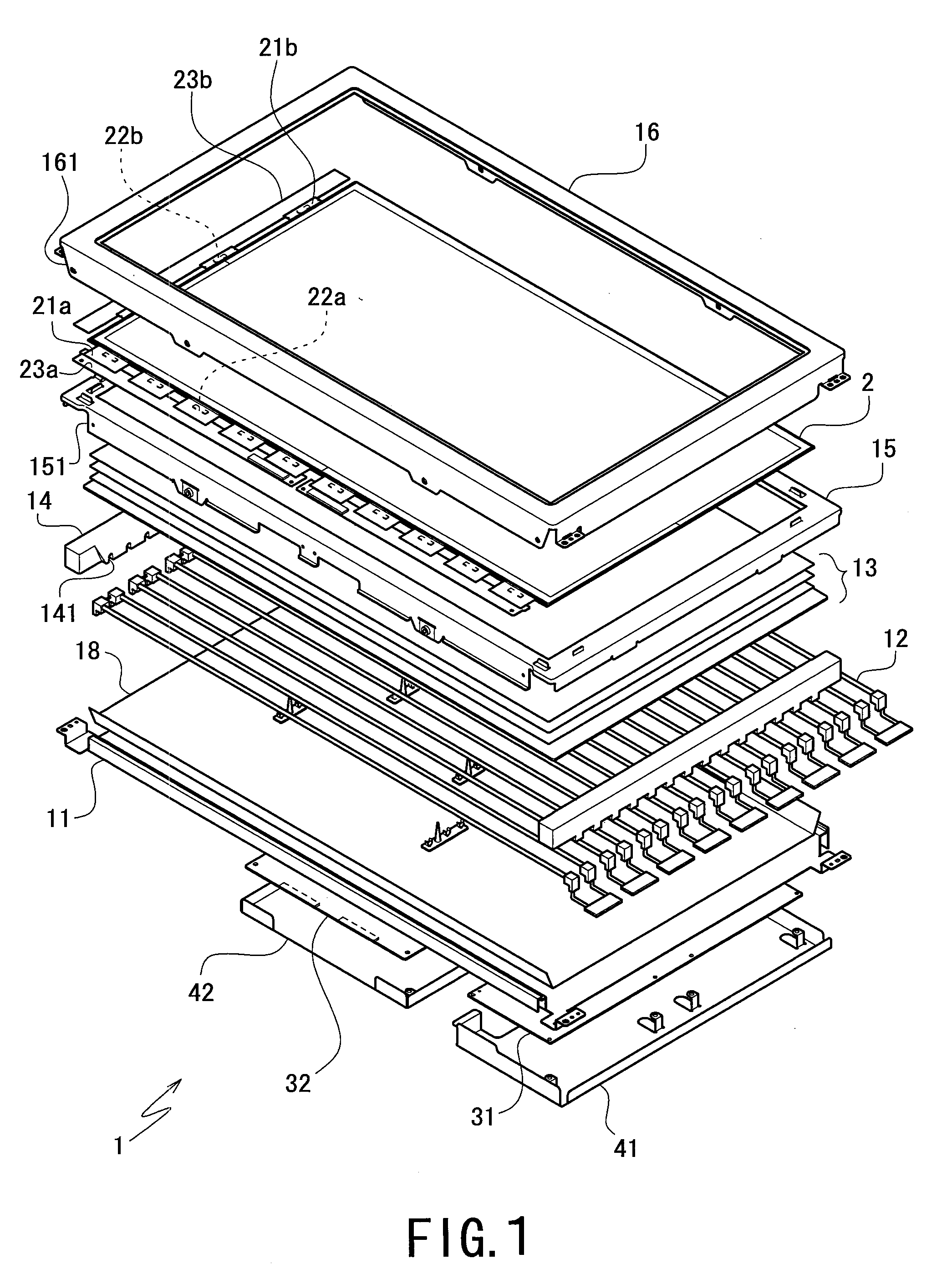
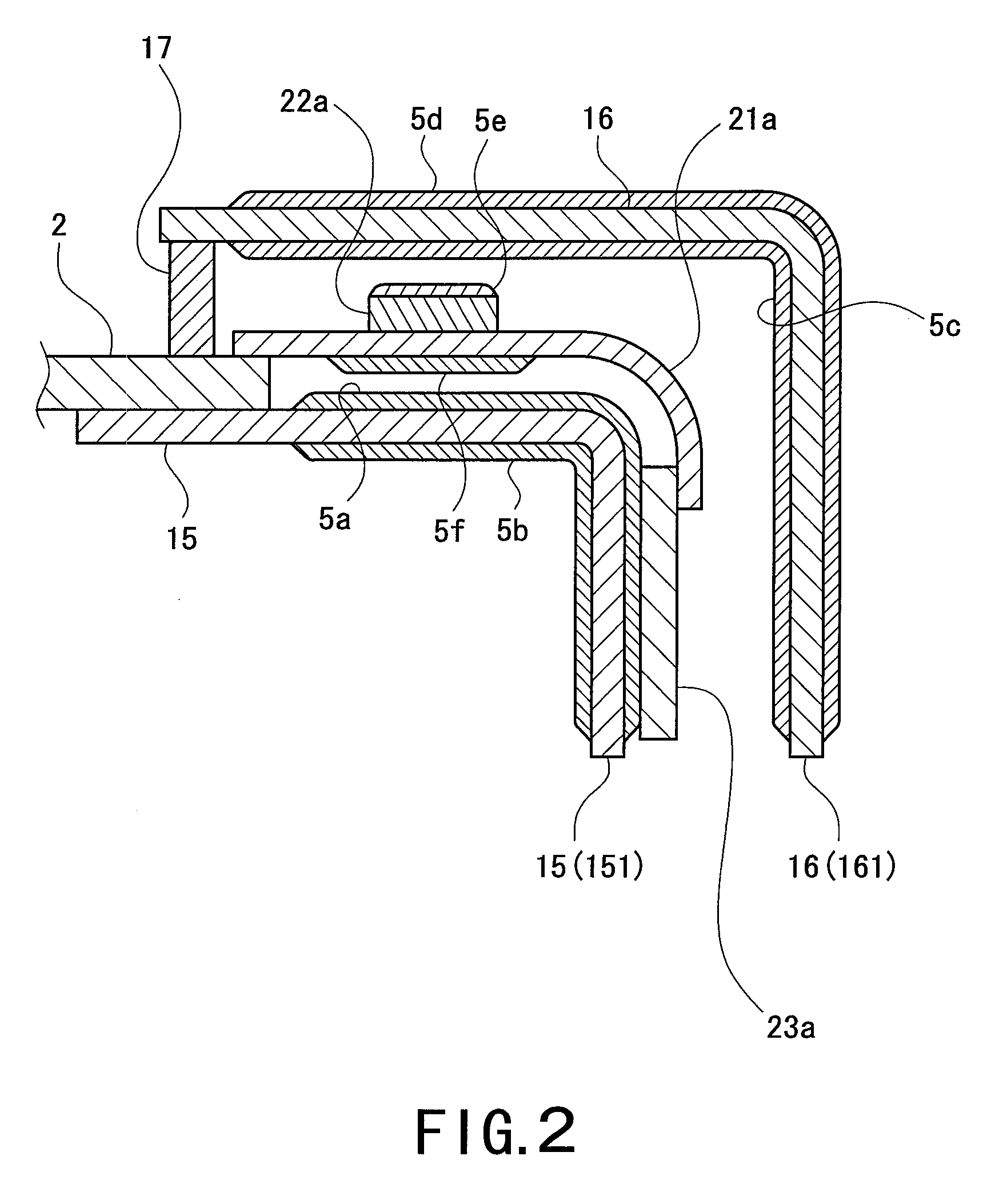
[0076]Advantageous effects of the present invention were examined for the display device according to a preferred embodiment of the present invention. Specifically, surface temperatures at the time of operation of the display device were measured for the source driver IC, the primary side transistor of the inverter circuit, and the control IC.
[0077]Table 1 shows a comparison of Examples according to a preferred embodiment of the present invention and Comparative Example. In a configuration of

Problems solved by technology

Especially, the source driver ICs, a control IC mounted on the control circuit board, and a primary side transistor of an inverter circuit mounted on the inverter circuit board generate a large quantity of heat since a large current flows therethrough.
In addition, recent increases in the size of the liquid makes the current flowing through the electronic or electrical components larger, thus making the quantity of generated heat larger.
However, in this configuration, the radiating fin should be brought into intimate contact with the electronic or electrical components in order to increase efficiency in cooling, and an excessive force is exerted on the electronic or electrical components.
Thus, there is a possibility that the electronic or electrical components are apt to come off the circuit boards or a film.
However, this configuration presents problems as described below.
First, an electric motor provided to the cooling fan as a rotation driving source has a lifetime far shorter than the lifetime of the liquid crystal panel or the lamp, which presents a problem in view of the design of the display device.
In addition, when the display device provided with the cooling fan is used in a television receiver or the like, a rotation sound made by the electric motor could be sometimes perceived as a noise by the user if the television receiver is used at a low sound level.
Such a generation of noise is not preferable in view of the quality of the display device.

Method used


Image

  • Display device and a televsion receiver having the same
  • Display device and a televsion receiver having the same
  • Display device and a televsion receiver having the same

Examples


example

[0075]A description of Examples according to various preferred embodiments of the present invention will be given.

[0076]Advantageous effects of the present invention were examined for the display device according to a preferred embodiment of the present invention. Specifically, surface temperatures at the time of operation of the display device were measured for the source driver IC, the primary side transistor of the inverter circuit, and the control IC.

[0077]Table 1 shows a comparison of Examples according to a preferred embodiment of the present invention and Comparative Example. In a configuration of Example 1, a ceramic coating was disposed on the inner surfaces of the bezel facing the source driver IC, the inverter circuit board cover facing the primary side transistor of the inverter circuit, and the control circuit board cover facing the control IC. In a configuration of Example 2, a ceramic coating was disposed on the surfaces of the source driver IC, the primary side trans...


PUM


Abstract

A display device is capable of efficiently cooling electronic or electrical components disposed therein without installing a cooling element or member on the electronic or electrical components. In the display device, a ceramic or ceramic-containing layer is formed on any one of a surface of a member placed in proximity to the electronic or electrical component, the surface facing at least the electronic or electrical component, a surface of the member placed in proximity to the electronic or electrical component, the surface opposite to the surface facing the electronic or electrical component, a surface of the electronic or electrical component, and a surface of a circuit board, the surface opposite to a surface of the circuit board on which the electronic or electrical component is mounted.

Description

BACKGROUND OF THE INVENTION[0001]1. Field of the Invention[0002]The present invention relates to a display device such as a liquid crystal display device and a television receiver having the same, and more specifically relates to a display device having a cooling mechanism arranged to cool electronic or electrical components disposed inside the display device and a television receiver having the same.[0003]2. Description of the Related Art[0004]A generally used translucent liquid crystal display device, which is cited as an example of display devices, includes a liquid crystal panel arranged to display an image and a lamp as a light source disposed behind the liquid crystal panel. Light emitted from the lamp passes through the liquid crystal panel, making an image displayed visible on a front side of the liquid crystal panel.[0005]On a peripheral portion of the liquid crystal panel, TABs on which source driver ICs, gate driver ICs and the like are mounted and a printed circuit board...

Claims


Application Information

Patent Timeline
IPC IPC(8): H05K5/00G02F1/1333
CPCG02F1/133308G02F1/133385H05K2201/10681H05K1/0203H05K1/189G02F2001/133314G02F1/133314
Inventor TAKATA, YOSHIKI
Owner SHARP KK
Learn More