
Recording/reproducing apparatus and recording/reproducing method

Inactive Publication Date: 2009-09-17
RICOH KK +1
View PDF20 Cites 0 Cited by
  • Summary
  • Abstract
  • Description
  • Claims
  • Application Information

AI Technical Summary

Benefits of technology

[0017]According to an embodiment of the present invention, a recording / reproducing apparatus and a recording / reproducing method may be provided capable of controlling the ratiational speed of a recording disk and stabilizing the surface vibration based on the consideration of the load of the spindle motor, when the recording disk is being rotated fast and the rotational speed is controlled.

Problems solved by technology

Therefore, it may not possible to adaptively adjust the distance between the stabilization member and the recording disk to the optimal distance based on the considerations of the change over time and the load of the spindle motor.
Therefore, it may be extremely difficult to obtain desirable characteristics in a very fast driving condition at, for example, 15,000 rpm or more and the rotational speed range where this technology can be used may be limited.
Therefore, it may be extremely difficult to apply this configuration (method) to a disk in which the recording / reproducing head is optically and macroscopically separated from the surface of the disk during operations.
Therefore, the opening may cause air disturbance which may limit the fast rotational speed of the disks and may not provide the desired characteristics when the fast-driven disk exceeds, for example, 10,000 rpm.

Method used


Image

  • Recording/reproducing apparatus and recording/reproducing method
  • Recording/reproducing apparatus and recording/reproducing method
  • Recording/reproducing apparatus and recording/reproducing method

Examples


first embodiment

[0038]Before describing a first embodiment, the experiments and comments on the experiments are described.

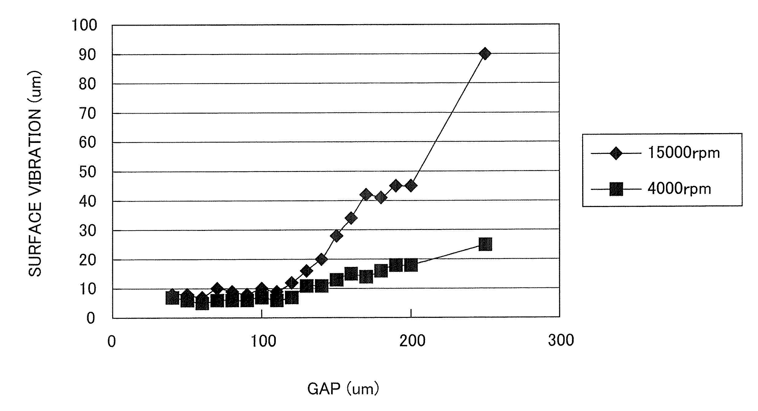
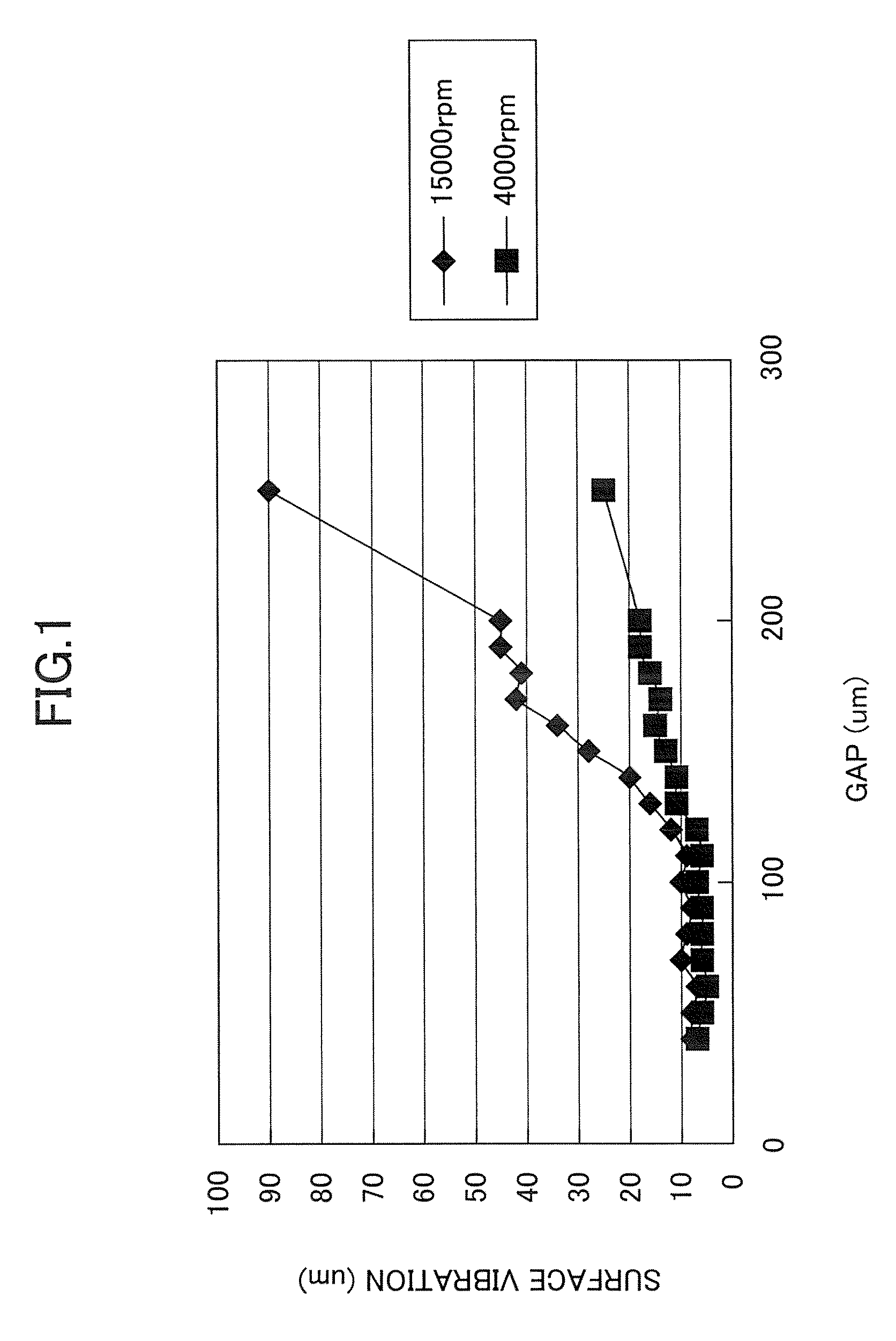
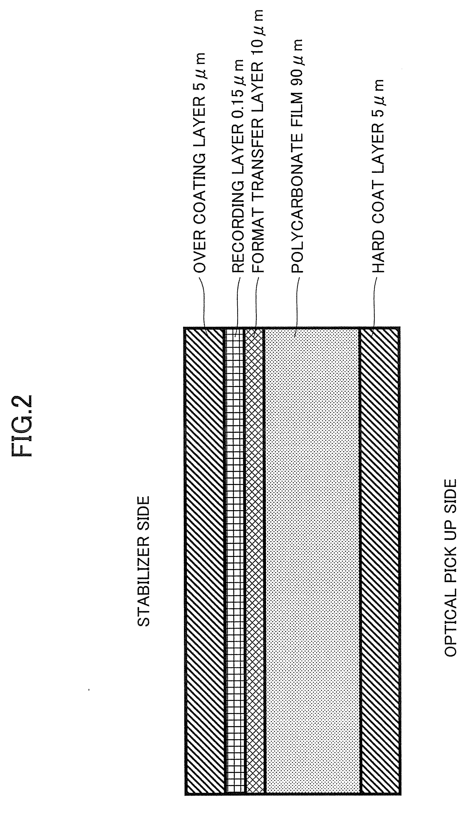
[0039]FIG. 1 shows a relationship between a gap (a distance between the disk and the stabilization member) and the amount of the surface vibration (hereinafter may be simplified as “surface vibration”) when a recording disk shown in FIG. 2 is used. FIG. 2 shows a configuration of the recording disk. The recording disk has a diameter 120 mm and a thickness about 110 μm and made of polycarbonate. As shown in FIG. 2, from a side facing an optical pickup to a side facing a stabilization member (stabilizer), the recording disks includes a hard coat layer (5 μm in thickness), a polycarbonate film (90 μm), a format transfer layer (10 μm), a recording layer (0.15 μm), and an over coating layer (5 μm).

[0040]Referring back to FIG. 1, FIG. 1 shows the changes of the amounts of surface vibration when the disk in FIG. 2 rotates at 15,000 rpm and 4,000 rpm, respectively. As shown in FIG. 1, w...

second embodiment

[0080]In the following, a recording / reproducing apparatus according to a second embodiment of the present invention is described. In this second embodiment, the optimum gap is determined based on the change of the rotational speed of the recording disk 500.

[0081]First, a relationship between the gap and the rotational speed is described with reference to FIG. 10. FIG. 10 shows the relationship between the gap and the rotational speed when the gap is set to 100 μm and a current or a voltage is set so that the recording disk 500 shown in FIG. 2 rotates at 10,000 rpm.

[0082]As shown in FIG. 10, when the gap becomes equal to or less than about 100 μm, the rotational speed decreases. Further, when the gap becomes less than about 40 μm, the spindle 502 stops. This stopping of the spindle 502 occurs because a deformed innermost part of the recording disk 500 starts sliding toward the stabilizer 507 due to the fact that the gap becomes too narrow.

[0083]Therefore, in this second embodiment, t...

modified embodiment

[0095]Next, a modified second embodiment of the present invention is described. This modified second embodiment is different from the second embodiment in that the optimum gap is determined not based on the change (difference) between before and after rotational speeds but based on a difference from a reference rotational speed.

[0096]FIG. 13 is a flowchart showing a process of determining the optimum gap according to the modified second embodiment of the present invention. In FIG. 13, the same numerals are used to designate the same or similar processes in FIGS. 7 and 12, and the descriptions thereof are omitted.

[0097]In step S1301, the calculation means 1102 determines whether the acquired (detected) rotational speed is equal to or less than a predetermined number. Herein, the predetermined number refers to a rotational speed which is less than a reference rotational speed by some percentage. In the example of FIG. 10, the reference rotational speed is set to the initial rotational...


PUM


Abstract

A recording / reproducing apparatus is disclosed that includes a spindle motor unit including a spindle on which a flexible recording disk is placed, a stabilizer plate disposed so as to face the recording disk, a torque detection unit configured to detect a drive torque applied to the spindle motor unit, an adjustment unit configured to adjust a gap between the recording disk and the stabilizer plate, and a determination unit configured to determine an optimal gap to be set to the gap based on the drive torque detected by the torque detection unit, in which the adjustment unit sets the optimum gap determined by the determination unit to the gap.

Description

CROSS-REFERENCE TO RELATED APPLICATIONS[0001]The present application claims priority under 35 U.S.C §119 to Japanese Patent Application No. 2008-066749 filed Mar. 14, 2008, the entire contents of which are hereby incorporated herein by reference.BACKGROUND OF THE INVENTION[0002]1. Field of the Invention[0003]The present invention generally relates to a recording / reproducing apparatus and a recording / reproducing method.[0004]2. Description of the Related Art[0005]As the digitization of television signals and the like has recently started, there is a growing demand for an information recording medium to record a large amount of digital data. To that end, for example, in the optical disk field, reducing the size of the optical spot converged onto an optical disk is thought to be one of the basic solutions for achieving high-density recording. (Herein, an optical disk is described as a representative of disk-shaped media used in a recording / reproducing apparatus according to embodiments...

Claims


Application Information

Patent Timeline
IPC IPC(8): G11B27/36
CPCG11B7/0945G11B7/0946G11B33/148G11B33/08G11B33/12G11B19/28G11B23/033G11B25/04
Inventor ONAGI, NOBUAKIAMAN, YASUTOMOTAKAHASHI, MINORUTOKUMARU, HARUKITAKANO, YOSHIMICHIKOIDE, DAIICHI
Owner RICOH KK
Features
  • Generate Ideas
  • Intellectual Property
  • Life Sciences
  • Materials
  • Tech Scout
  • Unparalleled Data Quality
  • Higher Quality Content
  • 60% Fewer Hallucinations
Learn More