Waste toner conveying device and image forming apparatus

Inactive Publication Date: 2009-09-17
RICOH KK
View PDF3 Cites 8 Cited by
  • Summary
  • Abstract
  • Description
  • Claims
  • Application Information

AI Technical Summary

Benefits of technology

[0045]An object of the present invention is to provide a waste toner conveying device and an image forming apparatus where waste toner having high flowability discharged from a conveying path of one cleaning device is flowed into a conveying path of anoth

Problems solved by technology

Under difficult circumstances where a paper having large amount of paper powder is used, an image area is not small, that is, amount of the waste toner is also small and therefore a mixed ratio of paper powder in the waste toner is relatively increased, or temperature in the apparatus is increased due to continuous working of the image forming apparatus, the flowability of the waste toner which may have paper powder is decreased so that the toner is easily clogged at the delivery part.
However, there is a problem in that the delivery parts 222, 223 may be clogged with the waste toner due to the low flowability of the waste toner passing through the delivery parts 222, 223 under the above-mentioned difficult circumstances.
However, there is a problem in that the combined part 321 may be clogged with the waste toner because the waste toner passing one of the two combined paths has flowability lower than that passing the other one of the two combined paths under the above-mentioned difficult circumstances.
However, there is a problem in that the delivery part 420 may be clogged with the waste toner because of low flowability under the above-mentioned difficult circumstances.
Furthermore, there is a problem in that the combined part 421 may be clogge

Method used


Image

  • Waste toner conveying device and image forming apparatus
  • Waste toner conveying device and image forming apparatus
  • Waste toner conveying device and image forming apparatus

Examples


Example

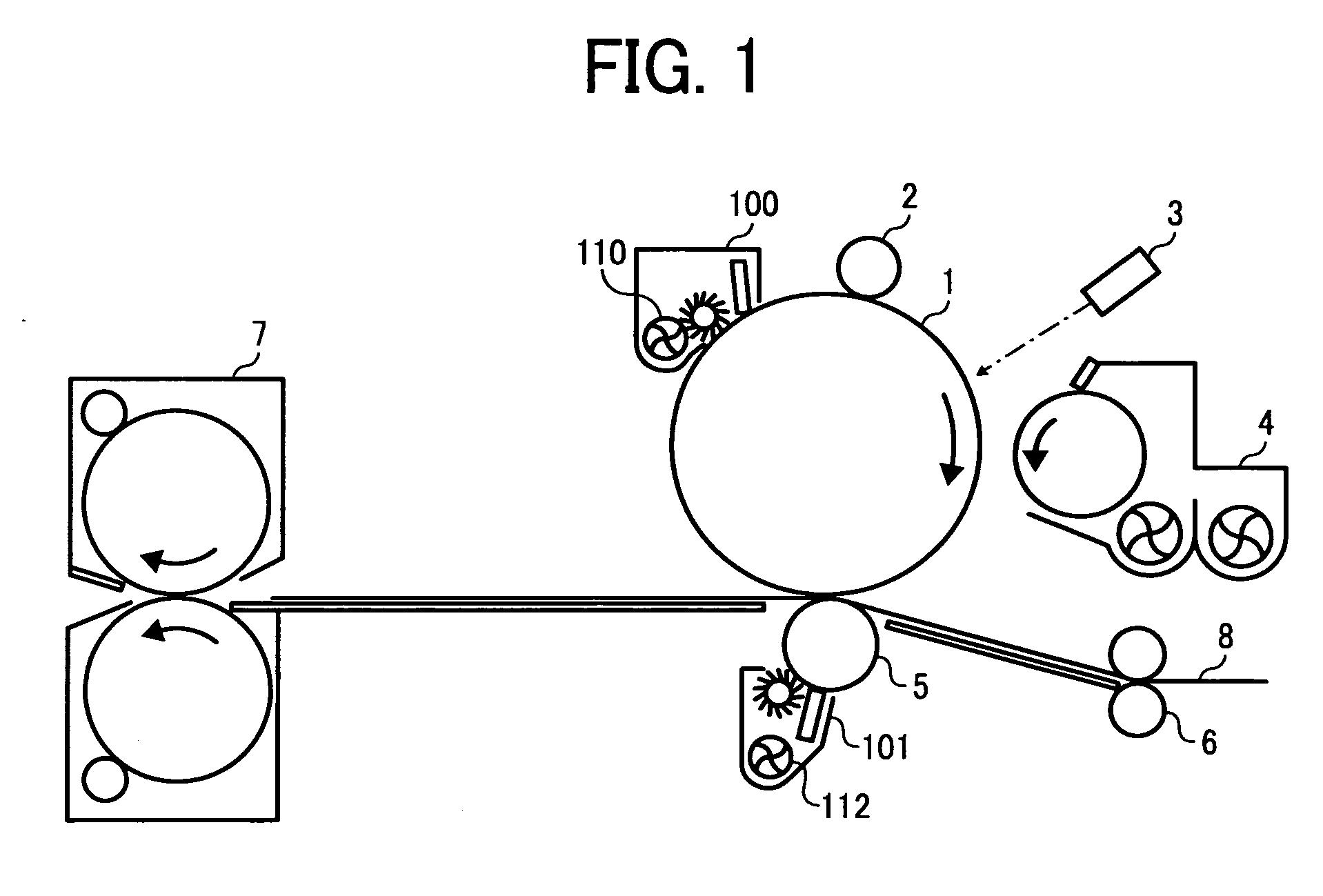
[0063]FIG. 1 is an explanatory view illustrating a layout of an image forming part of a first embodiment of the present invention. The configurations are explained hereinbefore and therefore the same reference numbers are used for the same configurations and explanation thereof is omitted.

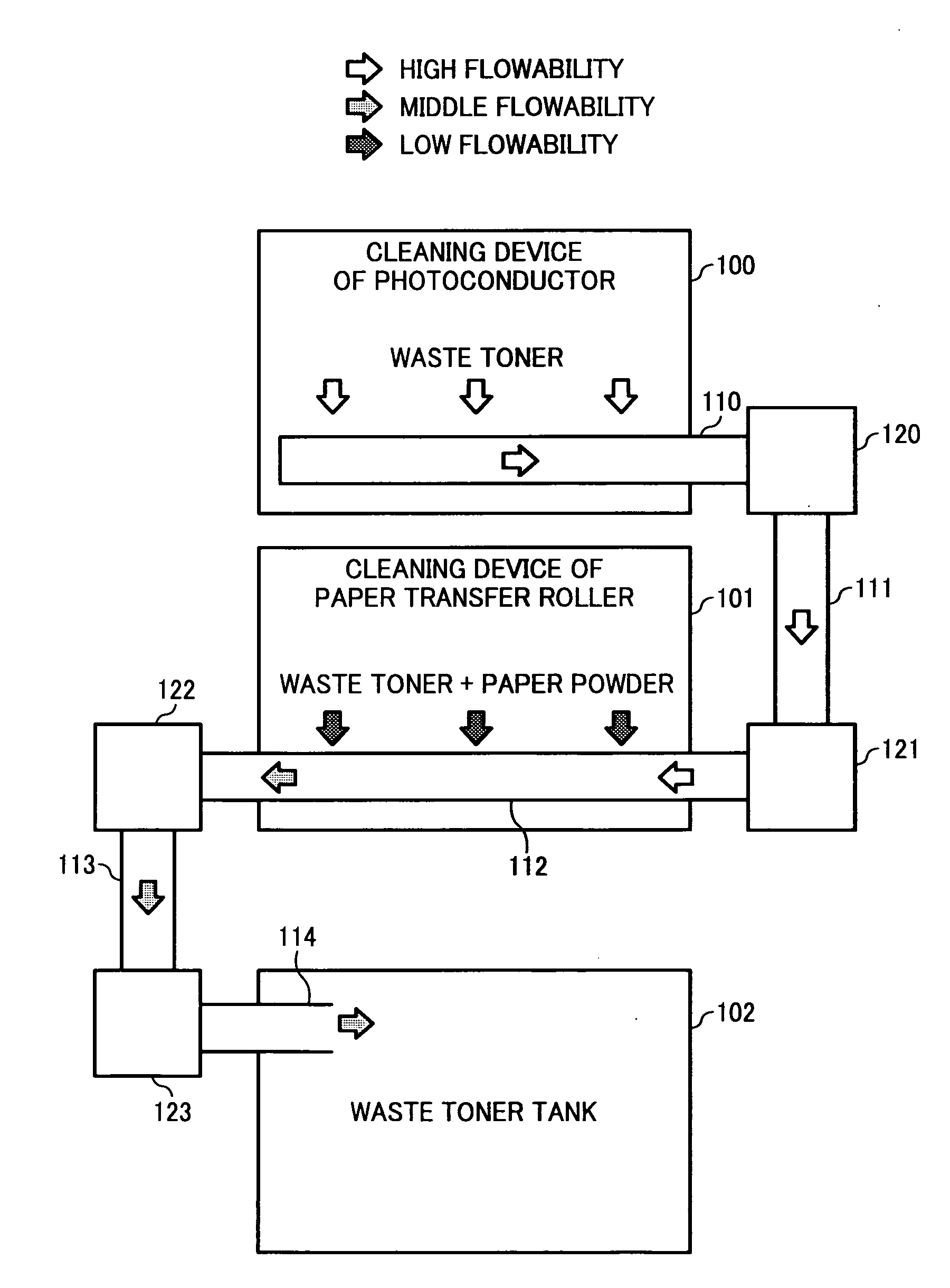
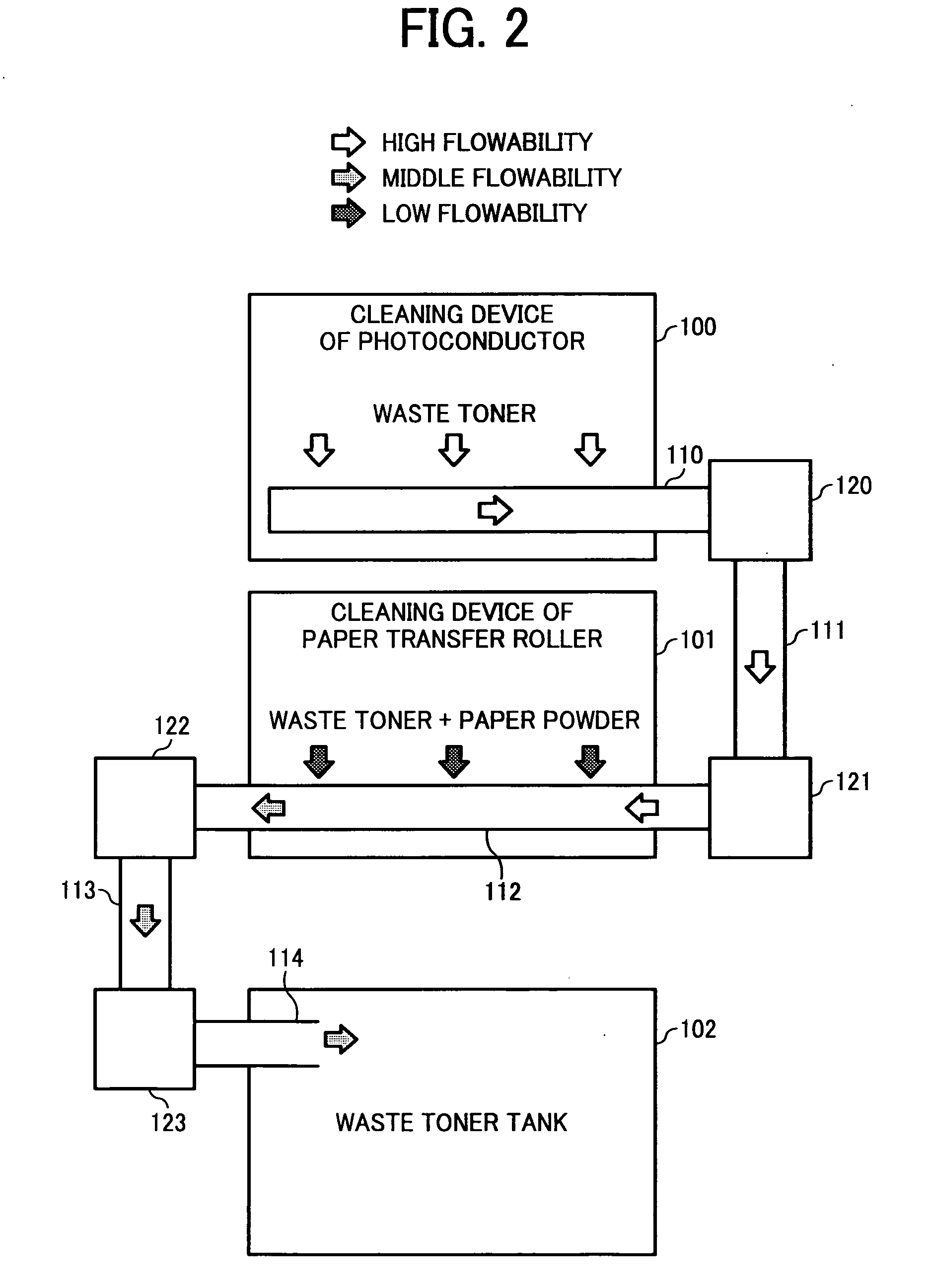
[0064]FIG. 2 is a schematic view illustrating flowabilities of waste toners and conveying directions for conveying the waste toner in waste toner conveying and forwarding paths in the waste toner conveying device according to the first embodiment. In FIG. 2, arrows indicate directions where the waste toner is conveyed and patterns in arrows indicate flowabilities of the waste toner, that is, a blanked arrow indicates high flowability, a mesh arrow indicates middle flowability, and filled arrow indicates low flowability. In FIG. 2, reference numbers 110, 111, 112, 113 and 114 indicate paths configured to convey the waste toner, and each path may have a conveying member configured to rotate for flowi...

Example

[0098]In the above-described waste toner conveying device according to the fifth embodiment, the delivery parts 1221, 1222, 1223, 1224, 1225, 1226 and the combined parts 1232, 1233, 1234 are not clogged with the waste toner because the waste toner passing therethrough has at least middle flowability (level 3) even under the difficult condition, for example, in continuous working at a high temperature.

(Comparison Between the Fifth Embodiment and Prior Art 7)

[0099]The delivery parts 1325, 1326 in the prior art 7 (see FIG. 15), are easily clogged with the waste toner under the above-mentioned difficult circumstances, more particularly, in continuous working at a high temperature, because the waste toner having relatively-low flowability passes and passes and flows together with each other. On the other hand, in the fifth embodiment of the present invention, the waste toner having relatively low flowability is mixed with the waste toner having relatively high flowability before it passi...


PUM


Abstract

A waste toner conveying device includes a first conveying path configured to convey waste toner having paper powder at a low mixed ratio, which is stored in a first cleaning device, outside the first cleaning device, a second conveying path configured to convey second waste toner having a paper powder at a high mixed ration, which is stored in a second cleaning device, outside the second cleaning device, and at least one forwarding path configured to convey the first waste toner conveyed from the first cleaning device through the first conveying path and the second waste toner conveyed from the second cleaning device through the second conveying path are conveyed to a waste toner storage device. The at least one forwarding path is configured to convey the first waste toner conveyed from the first cleaning device through the first conveying path to the waste toner storage device via the second conveying path.

Description

CROSS REFERENCE TO RELATED APPLICATIONS[0001]The present application is based on and claims priority from Japanese Application Numbers 2008-063788, filed on Mar. 13, 2008, and 2008-148100, filed on Jun. 5, 2008, the disclosure of which is hereby incorporated by reference herein in its entirety.BACKGROUND OF THE INVENTION[0002]1. Field of the Invention[0003]The present invention relates to a waste toner conveying device used in an image forming apparatus of electrophotographic system and an image forming apparatus.[0004]2. Description of the Related Art[0005]Generally, a color image forming apparatus has steps of forming toner images of four colors such as yellow (Y), magenta (M), cyan (C) and black (K) on one photoconductor or a plurality of photoconductors, overlapping the toner images on an intermediate transfer belt, transferring the overlapped toner images on a paper by a paper transfer roller and then fixing the transferred toner images. In such a color image forming apparatus,...

Claims


Application Information

Patent Timeline
IPC IPC(8): G03G21/00
CPCG03G15/0844G03G21/105G03G2221/0042G03G21/007
Inventor OZAWA, YOSHINORI
Owner RICOH KK
Why Eureka
Try Eureka