Heat exchange device for powder and granular material, and method for manufacturing the same

a technology of heat exchange device and granular material, which is applied in the direction of indirect heat exchanger, drying machine, light and heating apparatus, etc., can solve the problems of lowering the heat efficiency of the device, different types of block objects to be mixed, and requiring an enormous amount of time, so as to improve heat efficiency, enhance heat transfer, and reduce heat insulation effect

Inactive Publication Date: 2011-08-25
NARA MACHINERY
View PDF10 Cites 1 Cited by
  • Summary
  • Abstract
  • Description
  • Claims
  • Application Information

AI Technical Summary

Benefits of technology

[0014](a) The object to be processed adheres / accumulates in the angled parts other than the diagonal plate surface of the wedge of the heat exchanger, particularly in a section where the shaft and the wedge-shaped heat exchanger are attached. Adhesion / accumulation of the object to be processed reduces the heat-transfer area of the heat exchanger, lowering the heat efficiency of the device. Moreover, the adhered / accumulated object to be processed falls off of the heat exchanger as time advances, causing, in some cases or according to the heat history, different types of block objects to be mixed into the object to be processed.
[0018]The present invention was contrived in view of the above-described problems of the background art. An object of the present invention is to provide a heat exchange device for a powder and granular material, which is capable of suppressing an object to be processed from adhering / accumulating, while keeping high heat efficiency, piston flowability and other advantages of the conventional device that uses the wedge-shaped hollow rotating bodies, and reducing the man-hour of manufacturing processes (time). The present invention also aims to provide a method for manufacturing such heat exchange device.
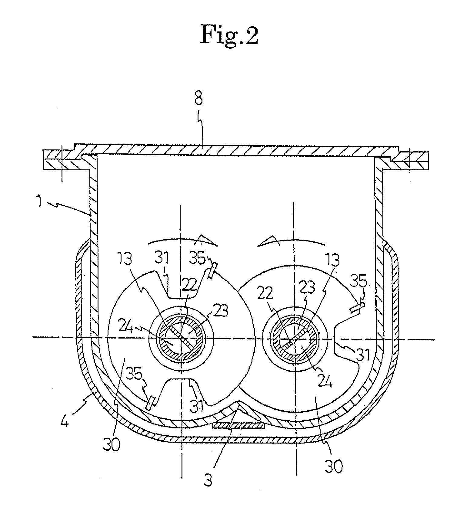
[0023]According to the heat exchange device for powder and granular material according to the present invention, each of the heat exchangers disposed on the shaft has a cutout recess part directed from a circumferential edge of the heat exchanger toward a center of the same, and plate surfaces extending from one side edge of the cutout recess part to another side edge of a following cutout recess part are formed into a wedge-shaped plate surface where the thickness of the plate surfaces increases gradually. Therefore, according to this heat exchange device, the gap between the wedge-shaped plate surfaces of two adjacent heat exchangers becomes gradually narrow from one side edge of the heat exchanger to the other side edge, and the heat exchanger cuts into a layer of an object to be processed as the shaft rotates. As a result, a compression force can be gradually acted on the layer of the object to be processed in the narrowing gap between the wedge-shaped plate surface, and the compression force can be released at once by the cutout recess part. Thus, the powder and granular material layer, which is the object to be processed, can be compressed and expanded repeatedly by the rotation of the shaft, whereby the powder and granular material can be heated or cooled efficiently. In other words, compressing the powder and granular material layer between the gradually narrowing wedge-shaped plate surfaces means compressing an internal air layer. Thus, lowering of a heat insulation effect and enhancement of heat transfer can be realized. On the other hand, the powder and granular material layer is released from the compression and expands at the cutout recess part located at a terminal end of the wedge-shaped plate surfaces, and consequently vaporized materials and the like contained in the gap between the powder and granular material can be emitted to the outside the system. Such a device of the present invention is capable of exerting the effect of repeatedly compressing and expanding the powder and granular material layer, to achieve high heat efficiency. Each of the heat exchangers used in the present invention has the cutout recess part directed from the circumferential edge of the heat exchanger toward the center of the same, as described above. Therefore, the heat exchange device can allow the passage of the object to be processed from the cutout recess part of the heat exchanger, ensuring the piston flowability of the object to be processed.
[0024]In addition, according to the heat exchange device for a powder and granular material according to the present invention, the projection that smoothly bulges in the horizontal direction as viewed from the side is formed at the central part of each heat exchanger, the tip end of the projection is formed into an opening, and the heat exchanger and the shaft are fixed by inserting the shaft into the opening. According to this heat exchange device, the section where the heat exchanger and the shaft are attached forms a smooth curved surface that does not allow the adhesion / accumulation of the object to be processed. As a result, the heat exchanger and the shaft can ensure a wide heat-transfer area, to realize the device having high heat efficiency. Moreover, the adherence or accumulation of the object to be processed is prevented, hence the falling off thereof and the mixing thereof into block objects do not occur, namely a highly reliable heat exchange operation for a powder and granular material can be realized.
[0025]In the heat exchange device for a powder and granular material according to the present invention, the entire configuration of each heat exchanger is in the shape of a substantially simple hollow disk. This allows the heat exchange device to reduce the man-hour of manufacturing processes (time) significantly in order to achieve easy automation of the welding operation.
[0026]According to the method for manufacturing the above-described heat exchange device for a powder and granular material according to the present invention, when fabricating each of the heat exchangers it is only necessary to perform only one welding operation on the peripheral edge part thereof where the two pieces of press-formed members abut on each other (there is only one weld line). Thus, the welding operation can be performed in a short time, facilitating the automation of the welding operation. When fixing each heat exchanger to the shaft, it is only necessary to insert the shaft into the opening formed in the heat exchanger, and to weld the heat exchanger to the shaft at the opening peripheral edge. This leads to a simple welding operation and a significant reduction of the welding time. In this case as well, since only one weld line is formed, the automation can be realized incredibly easily.

Problems solved by technology

The device described in Patent Literature 1, however, had the following problems:
(a) The object to be processed adheres / accumulates in the angled parts other than the diagonal plate surface of the wedge of the heat exchanger, particularly in a section where the shaft and the wedge-shaped heat exchanger are attached. Adhesion / accumulation of the object to be processed reduces the heat-transfer area of the heat exchanger, lowering the heat efficiency of the device. Moreover, the adhered / accumulated object to be processed falls off of the heat exchanger as time advances, causing, in some cases or according to the heat history, different types of block objects to be mixed into the object to be processed.
(b) The production of the shaft provided with the wedge-shaped hollow rotating bodies requires an enormous amount of time. In other words, each wedge-shaped hollow rotating body 50 is fabricated by disposing the two pieces of fan-shaped plate materials 51, 51, an isosceles triangular plate material 52, and a trapezoidal plate material 53 in the manner shown in FIG. 13 and welding the entire periphery of the abutment parts between these materials. Therefore, when forming a single heat exchanger, there are many steps in the welding process alone, and automation of the welding operation is difficult. Furthermore, when fixing each of the obtained heat exchangers to the shaft 60, plate material 61 formed with cutout holes which are substantially the same shape as a part (opening) of each heat exchanger that is in contact with the shaft 60, is lined (welded) on the entire outer peripheral surface of the shaft 60, and thereafter the plate material 61, the shaft 60 and the parts of the heat exchangers abutting on the plate material 61 and the shaft need to be welded at the entire periphery of the abutting sections. In addition, in such welding, the welding methods of each layer need to be changed. For this reason, the problem of the device described in Patent Literature 1 is that an enormous amount of time is required in fabricating the heat exchangers.
The heat exchanger with such a configuration, however, cannot ensure the piston flowability of the object to be processed, which are the excellent characteristic of the wedge-shaped hollow rotating body disclosed in Patent Literature 1.
Thus, in the case of such simple hollow disk-shaped rotating bodies, the piston flowability cannot be realized.

Method used


Image

  • Heat exchange device for powder and granular material, and method for manufacturing the same
  • Heat exchange device for powder and granular material, and method for manufacturing the same
  • Heat exchange device for powder and granular material, and method for manufacturing the same

Examples


Embodiment Construction

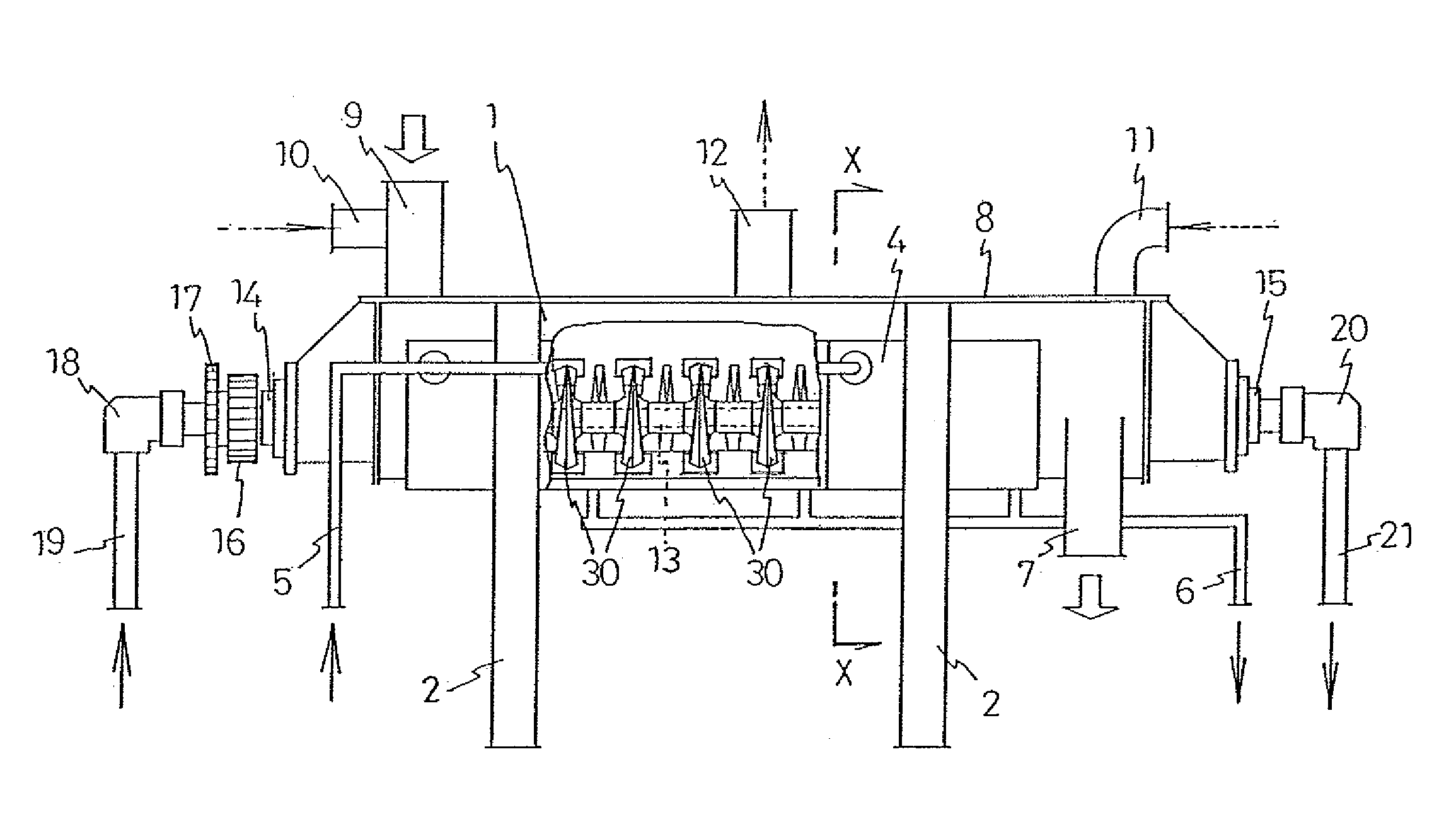
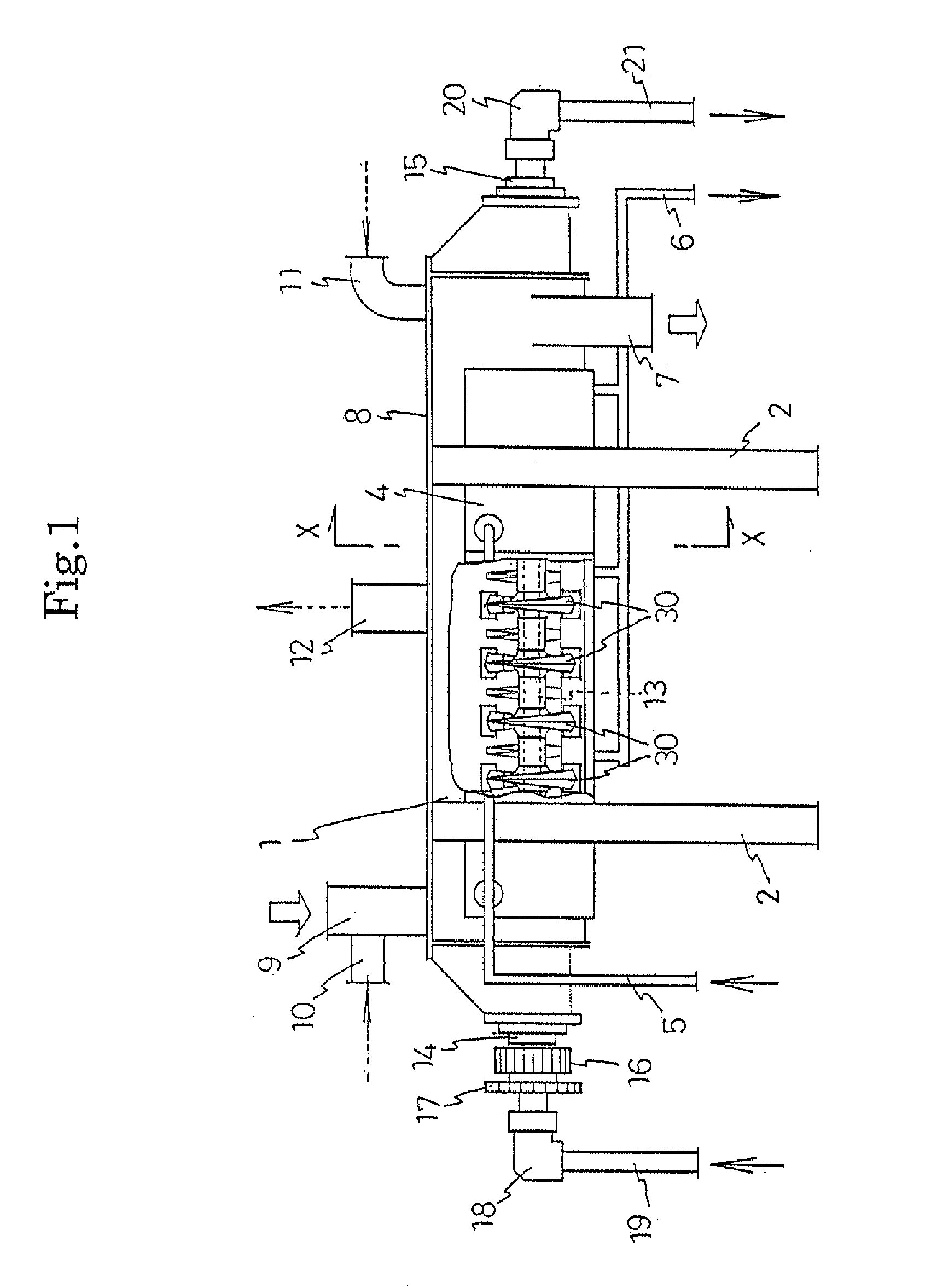
[0040]Embodiments of the abovementioned heat exchange device for a powder and granular material according to the present invention and a method for manufacturing such a heat exchange device are now described in detail with reference to the drawings.

[0041]In FIGS. 1 and 2, reference numeral 1 represents a casing of the heat exchange device, which is a relatively horizontally long container. This casing 1 is slightly inclined by supports 2 according to need. As shown in FIG. 2, the cross section of the casing 1 is in the shape of a bowl defined by two circular arcs. At a central bottom part of the bowl, a raised body 3, formed into a convex shape by the circular arcs, runs in a front-to-rear direction of the casing 1. A heat exchange jacket 4 is provided on substantially the entire surface including bottom and side surfaces of the casing 1.

[0042]As shown in FIG. 1, a supply pipe 5 and discharge pipe 6 for supplying and discharging a heat exchange medium are connected to the heat excha...


PUM

PropertyMeasurementUnit
apex angleaaaaaaaaaa
distanceaaaaaaaaaa
shapeaaaaaaaaaa

Abstract

An object of the present invention is to provide a heat exchange device for a powder and granular material, which is capable of suppressing an object to be processed from adhering / accumulating, and reducing the number of manufacturing processes (time), while keeping high heat efficiency, piston flowability and other advantages of a conventional device that uses wedge-shaped hollow rotating bodies. In order to achieve this object, a heat exchange device for a powder and granular material according to the present invention is configured such that at least one of a plurality of heat exchangers 30 to be disposed on a shaft 13 is formed as a substantially hollow disk-shaped heat exchanger in which a cutout recess part 31 directed from a circumferential edge of the heat exchanger toward a center of the same is provided; plate surfaces extending from one side edge 31a of the cutout recess part to another side edge 31b of a following cutout recess part are formed into a wedge-shaped plate surface 32 by gradually increasing a distance between the plate surfaces; a projection 33 that smoothly bulges in a horizontal direction as viewed from the side is formed at a central part of the heat exchanger; and an opening 34 is formed at a tip end of the projection, and the heat exchanger is disposed on the shaft by inserting the shaft into the opening.

Description

TECHNICAL FIELD[0001]The present invention relates to a heat exchange device for drying, heating or cooling a powder and granular material, and a method for manufacturing the heat exchange device.BACKGROUND ART[0002]An indirect heat transfer type grooved agitating dryer is known as a heat exchange device for drying, heating or cooling a variety of powder and granular materials.[0003]The device disclosed in, for example, Japanese Examined Patent Application Publication No. S48-44432 (Patent Literature 1, hereinafter) is known as such device.[0004]In the device disclosed in Patent Literature 1, a shaft, having a plurality of heat exchangers disposed at predetermined intervals, is rotatably supported within a horizontally long casing. A heat exchange medium is supplied into the heat exchangers via the shaft, and the heat exchangers are rotated within the casing. This device is structured such that a powder and granular material is dried (heated, cooled) by indirect heat transferred fro...

Claims


Application Information

Patent Timeline
Patent Type & Authority Applications(United States)
IPC IPC(8): F28F7/00B21D53/02
CPCF26B11/16F26B17/20F26B17/28Y10T29/4935F28D2021/0045F28F5/04F28D11/02F28D7/10
Inventor YOSHIHARA, ICHIRO
Owner NARA MACHINERY
Why Eureka
Try Eureka