Cylindrical steam reformer

a technology of cylindrical steam and reformer, which is applied in the direction of physical/chemical process catalysts, sustainable manufacturing/processing, bulk chemical production, etc., can solve problems such as equipment configuration complications, and achieve excellent heat transfer coefficient enhancement

Inactive Publication Date: 2010-10-07
TOKYO GAS CO LTD
View PDF1 Cites 16 Cited by
  • Summary
  • Abstract
  • Description
  • Claims
  • Application Information

AI Technical Summary

Benefits of technology

[0027]The cylindrical steam reformer according to the present invention has advantageous effects described under items (a) to (e) as follows,
[0028](a) Overall heat transfer coefficient can be excellently enhanced as compared with the case of using the granular reforming catalyst, more specifically, 1.3 times as high as that in the case of using the granular reforming catalyst,
[0029](b) A heat transfer area can be cut back as compared with the case of using the granular reforming catalyst with a heat transfer amount remaining the same, more specifically, by about 30% as compared with the case of using the granular reforming catalyst,
[0030](c) Variation in heat balance of the cylindrical steam reformer can be eliminated, thereby enabling the cylindrical steam reformer to be stably operated in the long term,
[0031](d) Each cell can be rendered smaller in size in an attempt to optimize the honeycomb reforming catalyst, and cell numbers, thereby reducing the heat transfer area,
[0032](e) Miniaturization of the cylindrical steam reformer itself can be implemented by virtue of those advantageous effects under (a) to (d) as above.

Problems solved by technology

Because the reforming catalyst among those catalysts, in particular, is used at a high temperature not lower than 600° C., for example, at around 700° C., if reactors provided with those catalysts, respectively, are disposed as separate units, there will arise needs for pipes, thermal insulating material, and so forth, for providing connection between the respective reactors, so that complication in equipment configuration will result.

Method used


Image

  • Cylindrical steam reformer
  • Cylindrical steam reformer
  • Cylindrical steam reformer

Examples


embodiments

[0162]The present invention is described in more detail hereinafter with reference to embodiments thereof, however, it goes without saying that the present invention is not limited thereto.

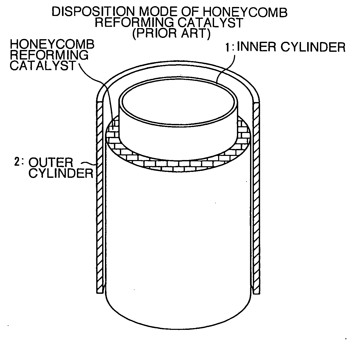
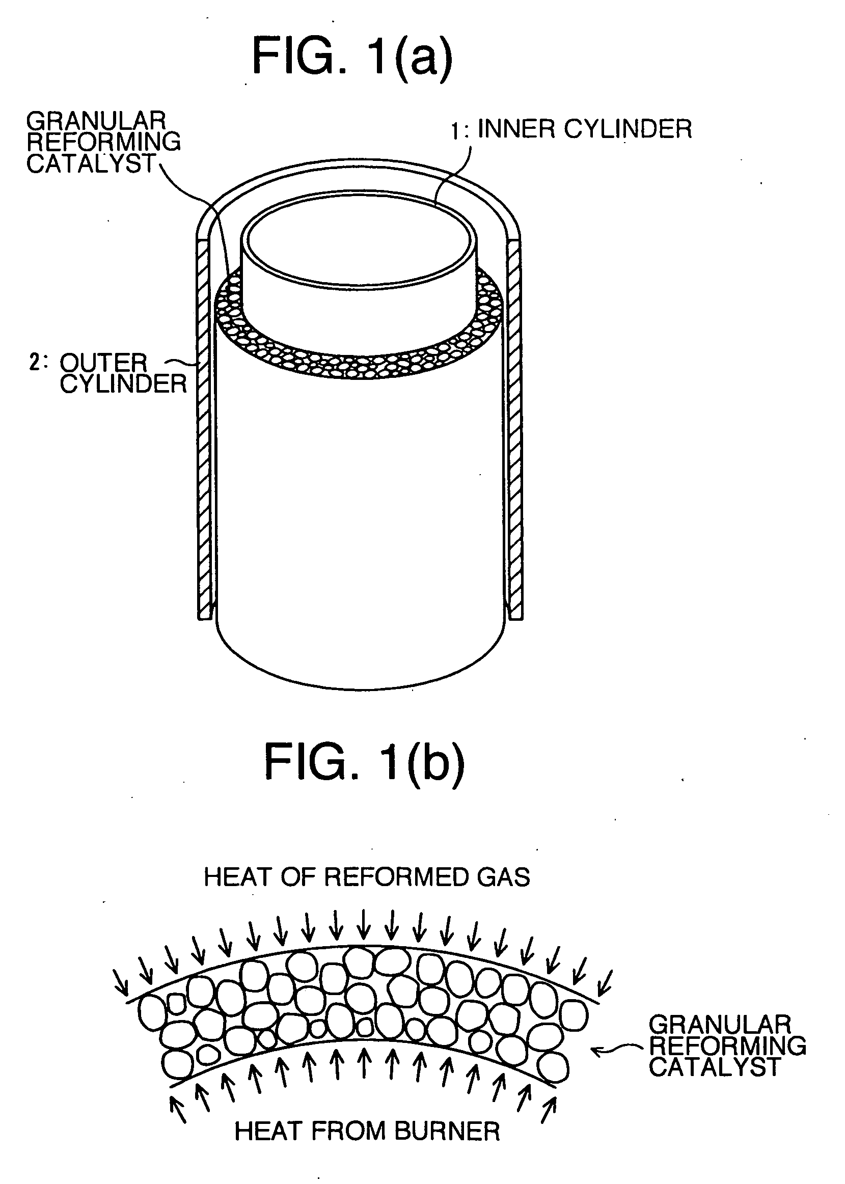
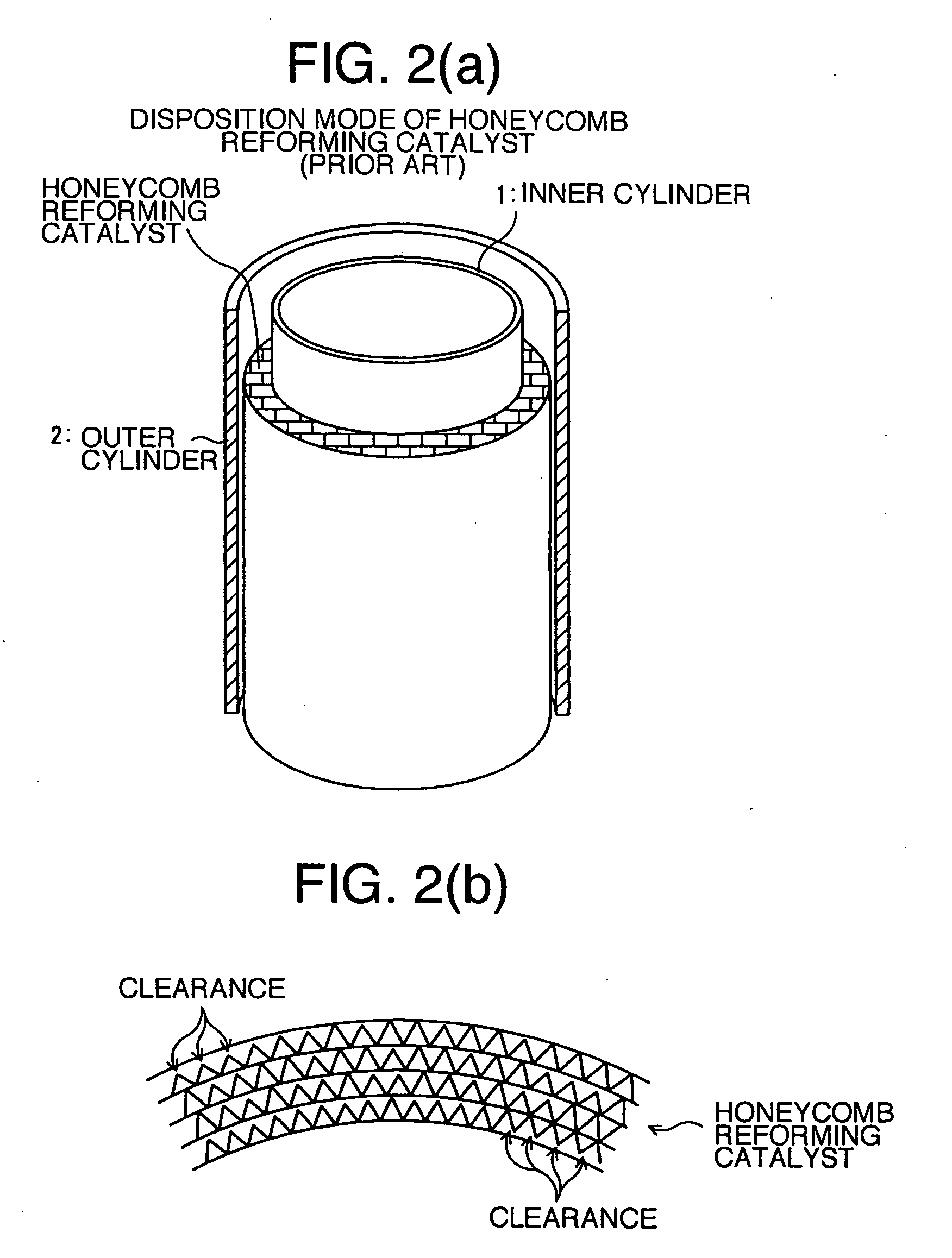
[0163]A cylindrical steam reformer wherein the granular reforming catalyst as shown FIGS. 1(a), 1(b) was disposed, a cylindrical steam reformer wherein the conventional honeycomb reforming catalyst as shown FIGS. 2(a), 2(b) was disposed, and a cylindrical steam reformer wherein the honeycomb reforming catalyst according to the present invention, as shown in FIGS. 6(a) to 6(c), was disposed were fabricated to be put to use, whereupon a performance test was conducted on each of the cylindrical steam reformers. Test conditions, and test results are as described in the attached Table 1.

[0164]In Table 1, the cylindrical steam reformer wherein the granular reforming catalyst was disposed is referred to as Comparative Example 1, and the cylindrical steam reformer wherein the conventional honeycomb reform...


PUM

PropertyMeasurementUnit
temperatureaaaaaaaaaa
heightaaaaaaaaaa

Abstract

A cylindrical steam reformer and process for manufacturing the same, wherein a honeycomb reforming catalyst is disposed in a clearance between an inner cylinder and an outer cylinder, making up a double cylinder. The cylindrical steam reformer improves thermal conductivity from the inner cylinder and the outer cylinder to the reforming catalyst.

Description

TECHNICAL FIELD[0001]The present invention relates to a cylindrical steam reformer, and more specifically, to a cylindrical steam reformer wherein a honeycomb reforming catalyst is disposed in a gap between an inner cylinder and an outer cylinder, making up a double cylinder, and an integrated cylindrical hydrogen production apparatus wherein the cylindrical steam reformer is incorporated in a cylindrical hydrogen production apparatus having a reforming catalyst layer, a CO conversion catalyst layer, and a CO removal catalyst layer so as to serve as the reforming catalyst layer thereof.BACKGROUND TECHNOLOGY[0002]In a hydrogen production apparatus for producing hydrogen as fuel of, for example, a polymer electrolyte fuel cell, use is made of a plurality of catalysts including a reforming catalyst, a CO conversion catalyst, and a CO removal catalyst. Because the reforming catalyst among those catalysts, in particular, is used at a high temperature not lower than 600° C., for example, ...

Claims


Application Information

Patent Timeline
Patent Type & Authority Applications(United States)
IPC IPC(8): B01J35/04
CPCB01J19/2485Y02E60/36B01J21/04B01J23/462B01J35/023B01J35/04B01J37/0225B01J37/0248B01J2219/2454B01J2219/2458B01J2219/2459B01J2219/2467B01J2219/2479B01J2219/2486B01J2219/2497C01B3/384C01B3/48C01B2203/0233C01B2203/044C01B2203/047C01B2203/0816C01B2203/0844C01B2203/0866C01B2203/1023H01M8/0618H01M8/0631H01M2008/1095Y02E60/50B01J19/249Y02P20/52Y02P70/50
Inventor ITSUKI, HISAYUKIFUJIKI, HIROSHIHONDO, MASAKI
Owner TOKYO GAS CO LTD
Why Eureka
Try Eureka