Solution cooling absorption type ammonia water motive power circulation device

A solution cooling and power cycle technology, which is applied in steam engine devices, machines/engines, mechanical equipment, etc., can solve the problems of reducing cycle thermal efficiency, and achieve the effects of improving cycle thermal efficiency, reducing temperature difference, and improving cycle efficiency

Inactive Publication Date: 2012-01-11
SOUTHEAST UNIV
6 Cites 17 Cited by

AI-Extracted Technical Summary

Problems solved by technology

However, if the mixture of ammonia and water is simply used as the circulating working fluid, although the endothermic evaporation process of the working fluid can achieve a temperature change matching the exothermic process of th...

Abstract

The invention discloses a solution cooling absorption type ammonia water motive power circulation device, which consists of an evaporator 1, a turbine machine set 3, a regenerator 4, a low-pressure absorbing device 5, a low-pressure ammonia pump 6, a gas-liquid separator 7, a pre-heater 8, a high-pressure absorbing device 9, a high-pressure ammonia pump 10, a throttle valve 11 and a connecting pipeline, wherein the low-pressure absorbing device and the high-pressure absorbing device are respectively divided into a solution cooling absorbing section and a cooling water absorbing section, and the solution cooling absorbing section is arranged above the cooling water absorbing section. The solution cooling absorption type ammonia water motive power circulation device has the advantages that the absorbing device outlet solution is used for cooling the front section of the absorbing process, the cooling water quantity can be reduced, the heat discharge and the heat transfer loss on the environment can be reduced, the heat transfer area is favorably reduced, and the circulation heat efficiency is favorably improved. The solution cooling absorption type ammonia water motive power circulation device is provided with the three-flow pre-heater for preheating work solution before entering the evaporator, the dilute solution and rich ammonia gas entering the absorber can be cooled, the absorption driving force can be enhanced, and in addition, the smoke gas low-temperature corrosion resistance of the device is favorably improved.

Application Domain

Technology Topic

Image

  • Solution cooling absorption type ammonia water motive power circulation device
  • Solution cooling absorption type ammonia water motive power circulation device

Examples

  • Experimental program(1)

Example Embodiment

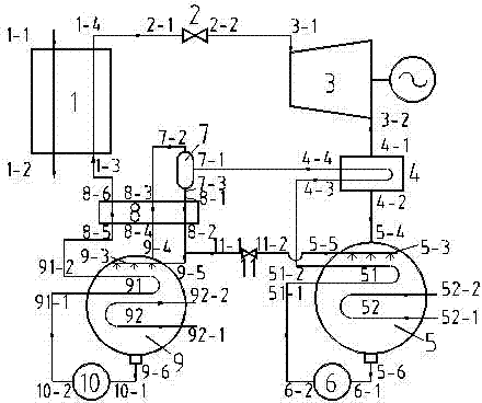
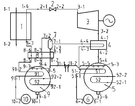
[0014] Example 1 see figure 1 , an ammonia water absorption power cycle device for power recovery and utilization of medium and low temperature heat sources, consisting of an evaporator 1, a turbine regulating valve 2, a turbine unit 3, a regenerator 4, a low-pressure absorber 5, a low-pressure ammonia pump 6, Gas-liquid separator 7, preheater 8, high-pressure absorber 9, high-pressure ammonia pump 10, dilute solution throttle valve 11 and connecting pipelines; evaporator 1 is provided with heat source fluid inlet 1-1 and heat source fluid outlet 1-2 , working solution inlet 1-3 and working solution outlet 1-4, regenerator 4 is provided with working solution inlet 4-1 and working solution outlet 4-2, basic solution inlet 4-3 and basic solution outlet 4-4, gas The liquid separator 7 is provided with a basic solution inlet 7-1, an ammonia-rich gas outlet 7-2 and a dilute solution outlet 7-3; it is characterized in that the low-pressure absorber 5 is divided into a solution cooling absorption section 51 and a cooling water absorption section 52, and the solution is cooled The inner channel of the absorption section 51 is provided with a basic solution inlet 51-1 and a basic solution outlet 51-2, the inner channel of the cooling water absorption section 52 is provided with a cooling water inlet 52-1 and a cooling water outlet 52-2, and the solution cooling absorption section 51 is arranged above the cooling water absorption section 52, and a dilute solution sprayer 5-3 and a gaseous working solution inlet 5-4 are also provided above the solution cooling absorption section 51. The inlet end of the dilute solution sprayer 5-3 It is the dilute solution inlet 5-5 of the low-pressure absorber, the basic solution outlet 5-6 is arranged at the bottom liquid bag of the low-pressure absorber 5, and the high-pressure absorber 9 is divided into a high-pressure solution cooling absorption section 91 and a high-pressure cooling water cooling absorption section 92. The inner channel of the solution cooling absorption section 91 is provided with a working solution inlet 91-1 and a working solution outlet 91-2, and the inner channel of the high pressure cooling water absorption section 92 is provided with a cooling water inlet 92-1 and a cooling water outlet 92-2. The solution cooling absorption section 91 is arranged above the high pressure cooling water cooling absorption section 92, and a high pressure dilute solution sprayer 9-3 and an ammonia-rich gas inlet 9-4 are also provided above the high pressure solution cooling absorption section 91. The inlet end of the sprayer 9-3 is the dilute solution inlet 9-5 of the high-pressure absorber 9, and the liquid sac at the bottom of the high-pressure absorber 9 is provided with a working solution outlet 9-6; the preheater 8 is a three-stream heat exchanger , with dilute solution inlet 8-1, dilute solution outlet 8-2, ammonia-rich gas inlet 8-3, ammonia-rich gas outlet 8-4, working solution inlet 8-5 and working solution outlet 8-6;
[0015] The connection relationship of each component is as follows: the working solution outlet 1-4 of the evaporator 1 is connected with the inlet 2-1 of the turbine regulating valve 2, and the outlet 2-2 of the turbine regulating valve is connected with the inlet 3-1 of the turbine unit 3 , the outlet 3-2 of the turbine unit is connected with the working solution inlet 4-1 of the regenerator 4, the working solution outlet 4-2 of the regenerator is connected with the working solution inlet 5-4 of the low pressure absorber 5, and the low pressure absorber The basic solution outlet 5-6 is connected with the inlet 6-1 of the low-pressure ammonia pump 6, the outlet 6-2 of the low-pressure ammonia pump 6 is connected with the basic solution inlet 51-1 of the low-pressure absorber 5 solution cooling absorption section 51, and the low-pressure solution is cooled. The basic solution outlet 51-2 of the absorption section 51 is connected to the basic solution inlet 4-3 of the regenerator, and the basic solution outlet 4-4 of the regenerator is connected to the inlet 7-1 of the gas-liquid separator 7, and the gas-liquid separator The ammonia-rich gas outlet 7-2 of 7 is connected to the ammonia-rich gas inlet 8-3 of the preheater 8, and the dilute solution outlet 7-3 of the gas-liquid separator 7 is connected to the dilute solution inlet 8-1 of the preheater 8, The ammonia-rich gas outlet 8-4 of the preheater is connected to the ammonia-rich gas inlet 9-4 of the high-pressure absorber 9, and the dilute solution outlet 8-2 of the preheater 8 is divided into two pipelines, one of which is connected to the high-pressure absorber 9. The dilute solution inlet 9-5 is connected, the other way is connected to the dilute solution throttle valve 11 inlet 11-1, and the dilute solution throttle valve 11 outlet 11-2 is connected to the dilute solution inlet 5-5 of the low pressure absorber; high pressure absorption The working solution outlet 9-6 of the device 9 is connected to the inlet 10-1 of the high-pressure ammonia pump 10, and the outlet 10-2 of the high-pressure ammonia pump 10 is connected to the working solution inlet 91-1 of the solution cooling and absorbing section 91 of the high-pressure absorber 9; The working solution outlet 91-2 of the solution cooling absorption section 91 of the absorber 9 is connected to the working solution inlet 8-5 of the preheater 8, and the working solution outlet 8-6 of the preheater is connected to the working solution inlet 1-3 of the evaporator 1 connect.
[0016] The workflow of the ammonia water power cycle is as follows:
[0017]The liquid of the ammonia water absorption power cycle working solution enters the evaporator to complete the endothermic process, evaporates into a gaseous working solution, and realizes the expansion work process in the turbine to complete the thermal power conversion; the turbine exhaust is first cooled in the regenerator, Then it enters the low-pressure absorber and is absorbed by the dilute solution sprayed on the tube bundle of the low-pressure absorber, and the released latent heat of vaporization is taken away by the basic solution and cooling water on the other side of the low-pressure absorber; the dilute solution absorbs the gaseous working solution and becomes The basic solution is collected at the bottom of the low-pressure absorber and flows out. After the basic solution is boosted by the low-pressure ammonia pump, the solution is heated and desorbed successively in the solution cooling and absorption section of the low-pressure absorber and in the regenerator, and becomes a gas-liquid two-phase Fluid, gas-liquid separation is carried out in the separator. The gas phase is ammonia-rich gas, and the liquid phase is dilute solution. The ammonia-rich gas and the dilute solution enter the preheater for cooling at the same time. After the ammonia-rich gas is cooled, it enters the high-pressure absorber. Divided into two paths, most of the dilute solution flows back to the low-pressure absorber through the throttle valve, and is sprayed on the absorber tube bundle. The latent heat of vaporization is carried away by the working solution and cooling water. The working solution collected at the bottom of the high-pressure absorber is boosted by the high-pressure ammonia pump, and then it absorbs heat in the solution cooling and absorption section of the high-pressure absorber and the preheater successively and then flows back to the evaporator to complete the evaporation process; the evaporator The gaseous working solution at the outlet then enters the turbine to expand and do work, and so on.

PUM

no PUM

Description & Claims & Application Information

We can also present the details of the Description, Claims and Application information to help users get a comprehensive understanding of the technical details of the patent, such as background art, summary of invention, brief description of drawings, description of embodiments, and other original content. On the other hand, users can also determine the specific scope of protection of the technology through the list of claims; as well as understand the changes in the life cycle of the technology with the presentation of the patent timeline. Login to view more.

Similar technology patents

Brushless Motor and System Thereof

InactiveUS20170047834A1Risk be eliminate and substantially reduceImprove energy conversion efficiencyAssociation with control/drive circuitsSalient polesControl systemBrushless motors
Owner:FOSTER ASSETS CORPORATION

Classification and recommendation of technical efficacy words

  • Reduce cooling water
  • Improve energy conversion efficiency

Water-saving environment-friendly cooling tower

PendingCN108917421AReduce cooling waterEasy to adjustHeat exchange apparatusTrickle coolersWater savingNozzle
Owner:德州贝泰制冷设备有限公司

Method for preparing semi-water gas with fixed bed

ActiveCN102344833AReduce cooling waterChemical industryGas purification by non-gaseous materials condensationZero emissionSewage
Owner:ANHUI JINGHE IND

Anti-stripping water quantity distribution method for hot continuous rolling machine

ActiveCN110276084AImprove anti-stripping abilityReduce cooling waterRolling equipment maintainenceDesign optimisation/simulationDistribution methodContinuous rolling
Owner:SHANGHAI MEISHAN IRON & STEEL CO LTD
Why Eureka
Try Eureka