Filler-reinforced solid resin multilayered structure

Inactive Publication Date: 2019-03-07
SABIC GLOBAL TECH BV
View PDF3 Cites 0 Cited by
  • Summary
  • Abstract
  • Description
  • Claims
  • Application Information

AI Technical Summary

Benefits of technology

The present invention relates to a filler-reinforced solid resin multilayered structure that has advantages over other filler-reinforced resins. The structure can be made using a wider variety of resins, is more easily recyclable or reprocessable, and can incorporate more thermo-formable features. It also has a higher proportion of filler aligned with one another or aligned in specific directions, equivalent or better mechanical properties, lower wt % loading of filler, and better transparency. The structure can be used to form a photomask box or part of a photomask box, wherein less or no particulate is formed during the cutting as compared to other filler-reinforced films.

Problems solved by technology

Although woven or non-woven mats, felts, and fabrics can be used to form reinforced resins such as glass fiber- or carbon fiber-reinforced resins having good mechanical properties, the reinforced resins are difficult and expensive to manufacture, and can have poor optical properties.
The types of resins that can be used to manufacture such reinforced resins are limited because the resins must be highly flowable to wet out the structure of the reinforcing material.
However, glass is heavy and brittle.
Transparent plastic sheets, such a polycarbonate, generally lack the needed stiffness unless used in a thickness that results in higher weight and thicker design than desired.
Although glass-reinforced film can be laminated on a transparent plastic sheet to enhance stiffness, such films have higher haze and glass-level transparency and glossiness around the border of the laminated structure can be very difficult.

Method used


Image

  • Filler-reinforced solid resin multilayered structure
  • Filler-reinforced solid resin multilayered structure
  • Filler-reinforced solid resin multilayered structure

Examples


example 1.1

uality

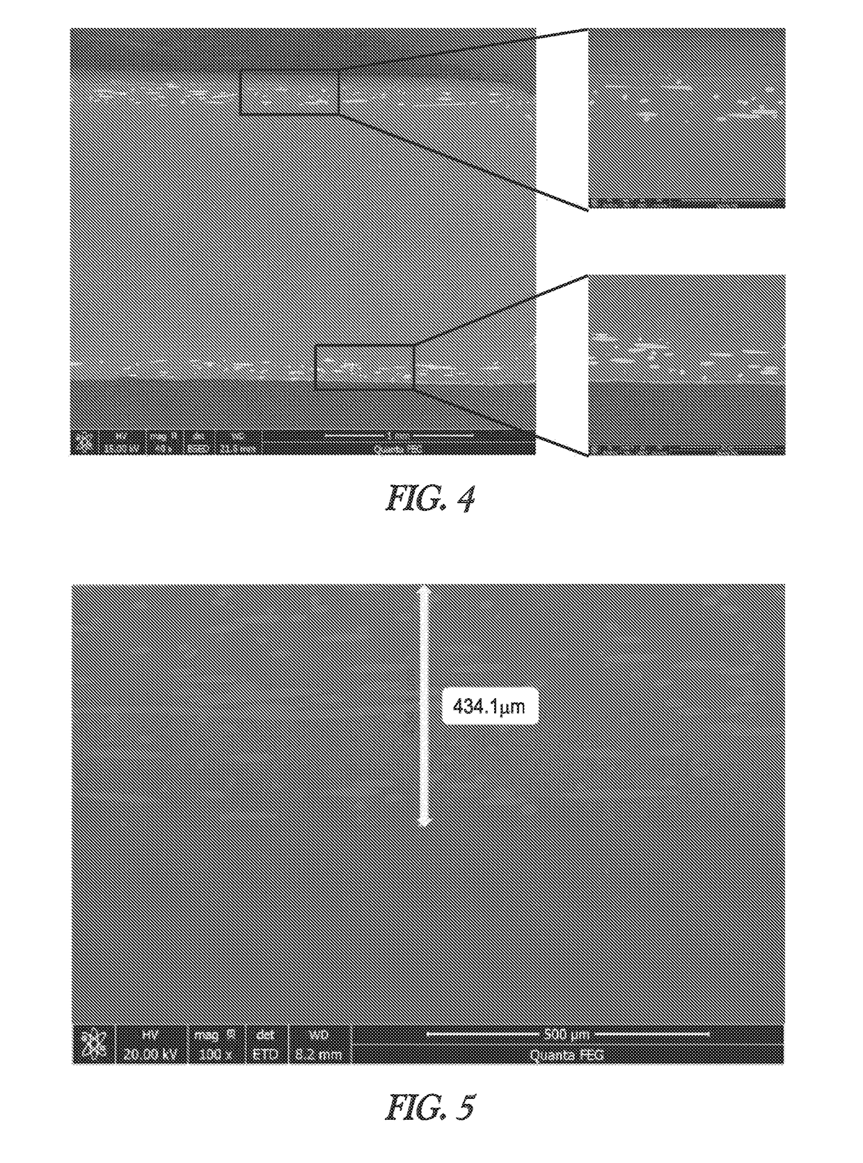
[0078]Two extruded 120 micron-thick glass fiber-filled films were placed on the top and bottom of a pressed glass fiber-free film such that the extrusion direction of each extruded film was in parallel. The press was preheated to 160° C. The stack was pressed from the top and bottom sides using the press at 160° C. for 5 seconds, followed by cooling by injecting 40° C. water into cooling channels in the press. FIG. 4 illustrates a scanning electron microscope (SEM) image of the laminated structure formed. No interface was visible between the layers of the laminated structure formed.

[0079]Three extruded 120 micron-thick glass fiber-filled films were placed together such that the extrusion direction of each extruded film was in parallel. The press was preheated to 160° C. The stack was pressed from the top and bottom sides using the press at 160° C. for 5 seconds, followed by cooling by injecting 40° C. water into cooling channels in the press. FIG. 5 illustrates a SEM image of ...

example 1.2a

ity and Flexural Modulus

[0081]On top on a pressed glass fiber-free film was laid 0, 1, 2, or 3 layers of extruded 120 micron-thick glass fiber-filled film such that the extrusion direction of each extruded film was in parallel. The press was preheated to 160° C. The stacks were pressed from the top and bottom sides using the press at 160° C. for 5 seconds, followed by cooling by injecting 40° C. water into cooling channels in the press. The transmittance and haze of the resulting structures were measured and are given in Table 1.

TABLE 1# of layers of glassfiber filled filmTransmittance [%]Haze [%]087.700.50186.651.59285.853.46385.006.61

[0082]The flexural modulus and increment rate of the structures were measured and are given in Table 2.

TABLE 2# of Layer ofChopped Glass-Fiber20% filled filmModulus [GPa]Increment Rate [%]01.2010012.9024224.1034234.70392

example 1.2b

ity, Flexural Modulus, and Impact Strength

[0083]On top on a pressed glass fiber-free film was laid 0 or 1 layer of extruded 120 micron- or 250 micron-thick glass fiber-filled film. The press was preheated to 160° C. The stacks were pressed from the top and bottom sides using the press at 160° C. for 5 seconds, followed by cooling by injecting 40° C. water into cooling channels in the press. The transmittance and haze of the resulting laminated structures were measured and are given in Table 3.

TABLE 3Thickness of layers ofglass fiber filled filmTransmittance[microns][%]Haze [%]087.700.5012086.651.5925086.003.61

[0084]The flexural modulus and increment rate of the structures were measured and are given in Table 4.

TABLE 4Chopped Glass-Fiber20% filled filmthicknessIncrement Rate[micrometer]Modulus [GPa][%]01.201001202.902422503.66305

[0085]The impact energy and retention rate of the structures were measured using a Dynatup impact test and are given in Table 5, with a 2 mm-thick injection ...


PUM

PropertyMeasurementUnit
Angleaaaaaaaaaa
Digital informationaaaaaaaaaa
Nanoscale particle sizeaaaaaaaaaa

Abstract

Filler-reinforced solid resin multilayered structures and methods of making the same. A filler-reinforced solid resin multilayered structure includes a laminated layer stack. The laminated layer stack includes an inner structure including a first resin layer that is a filler-reinforced resin layer including a cured product of a filler and a resin. The inner structure also includes a second resin layer including a cured product of a resin. The second resin layer is different than the first resin layer. The laminated layer stack also includes a border structure including at least one edge of the second resin layer extending past a corresponding edge of the first resin layer. The border structure is free of the first resin layer.

Description

CROSS-REFERENCE TO RELATED APPLICATION[0001]This application claims the benefit of priority to U.S. Provisional Patent Application Ser. No. 62 / 318,984, filed Apr. 6, 2016, and to U.S. Provisional Patent Application Ser. No. 62 / 395,469, filed Sep. 16, 2016, the disclosures of which are incorporated herein in their entirety by reference.BACKGROUND[0002]Although woven or non-woven mats, felts, and fabrics can be used to form reinforced resins such as glass fiber- or carbon fiber-reinforced resins having good mechanical properties, the reinforced resins are difficult and expensive to manufacture, and can have poor optical properties. The types of resins that can be used to manufacture such reinforced resins are limited because the resins must be highly flowable to wet out the structure of the reinforcing material.[0003]As display panel technology is moving from LCD to OLED, the enclosure design is changing toward highlighting the design characteristic of OLED which is thinner than LCD d...

Claims


Application Information

Patent Timeline
IPC IPC(8): B32B27/36B32B27/08B32B27/20B32B3/02B32B7/00B32B7/02B32B7/022
CPCB32B7/03B32B27/365B32B27/08B32B27/20B32B3/02B32B7/02B32B2262/101B32B2262/106B32B2264/101B32B2307/412B32B2307/418B32B2307/536B32B2307/546B32B2457/20B32B2307/41B32B2307/558B32B7/022B32B37/10B32B2398/20B32B2305/08B32B2307/538B32B37/06B32B37/18B32B2250/24
Inventor CHOI, JONG-MINAN, NARONGKIM, DAEJUN
Owner SABIC GLOBAL TECH BV
Why Eureka
Try Eureka