
Sternum closure device

a closure device and sternum technology, applied in the field of sternum closure devices, can solve problems such as substantial difficulties, and achieve the effect of great stability of the inner contact elemen

Inactive Publication Date: 2009-09-17
AESCULAP AG
View PDF21 Cites 166 Cited by
  • Summary
  • Abstract
  • Description
  • Claims
  • Application Information

AI Technical Summary

Benefits of technology

[0008]The outer contact elements can be removed relatively easily during any renewed operation; for this purpose it is sufficient to lift the clamping elements away. This is substantially more difficult in the case of the inner contact elements since these are not accessible. As a result of the construction of the inner contact elements from two parts which are separate from one another and of which each is associated with one sternum portion and as a result of the releasable connection of these two parts of the inner contact element, these two parts may be separated from one another after the connection is released and can, therefore, follow the separation of the sternum portions when these are spread apart. As a result, the inner contact elements do not hinder this spreading apart of the two sternum portions.
[0025]It may be provided for the contact elements to be coated with a material which prevents the bonding to bone material, for example, with polytetrafluoroethylene. As a result, it is easier to detach the contact elements from the surrounding bone material if a renewed separation of the sternum is necessary.

Problems solved by technology

This is substantially more difficult in the case of the inner contact elements since these are not accessible.

Method used


Image

  • Sternum closure device
  • Sternum closure device
  • Sternum closure device

Examples


Embodiment Construction

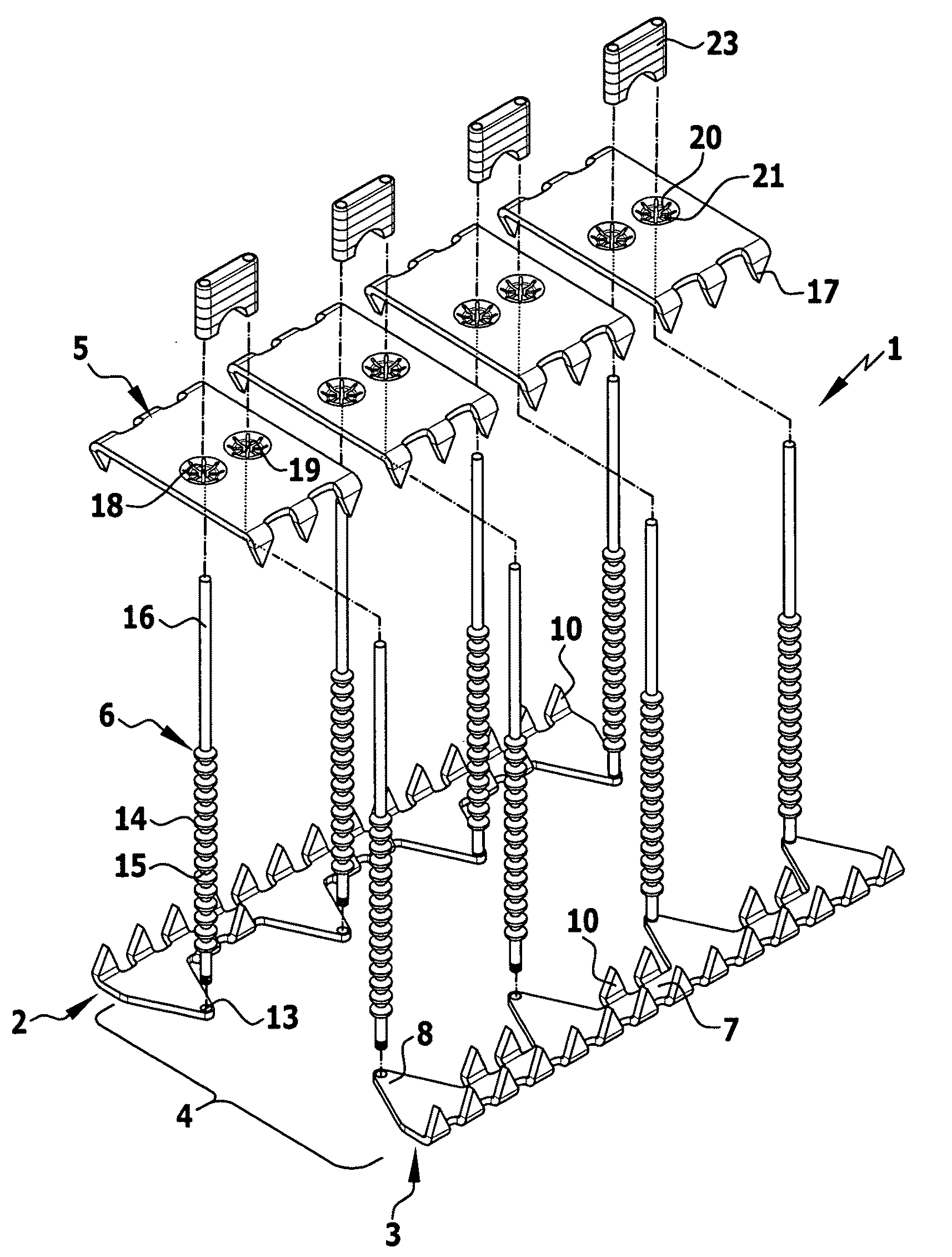
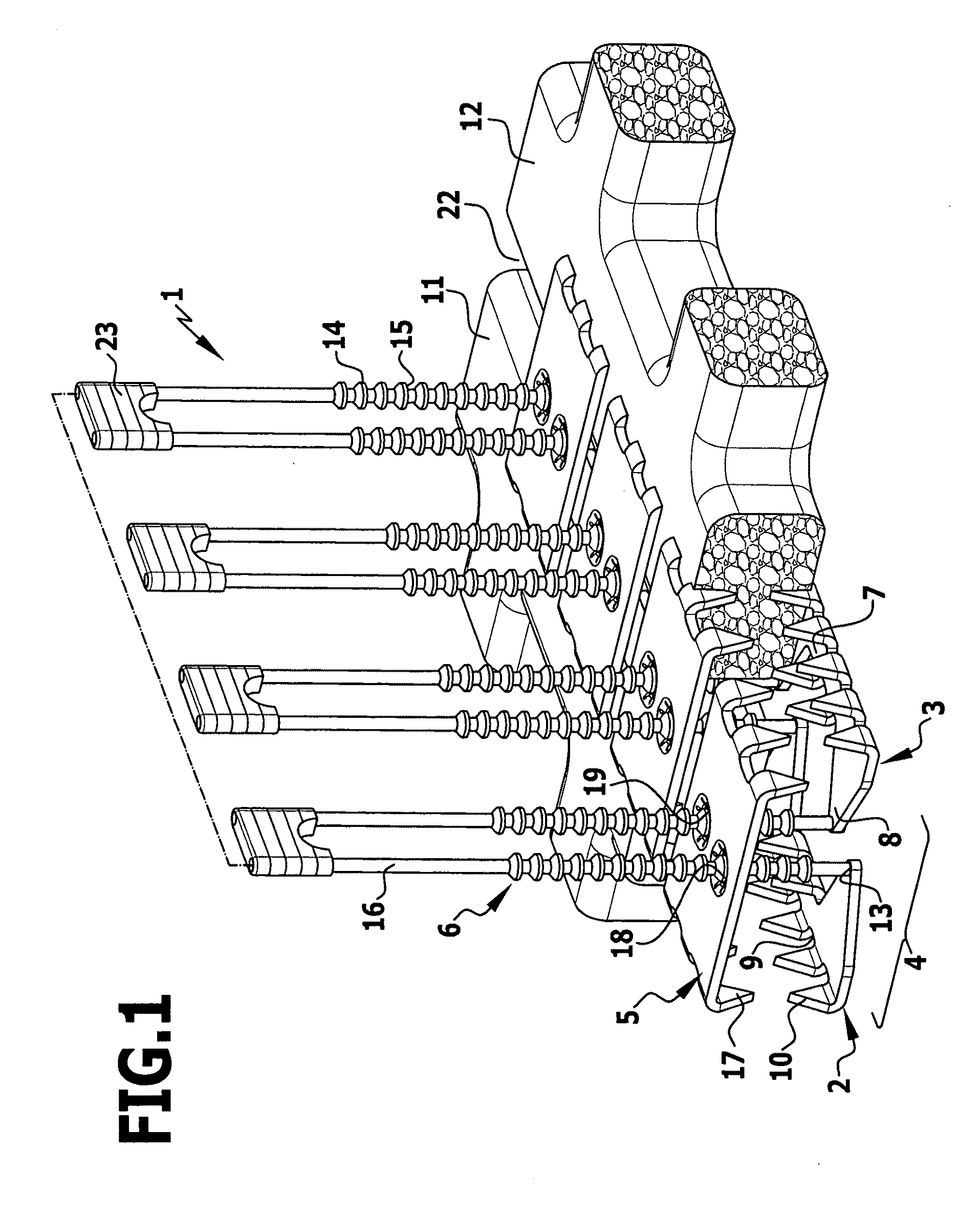
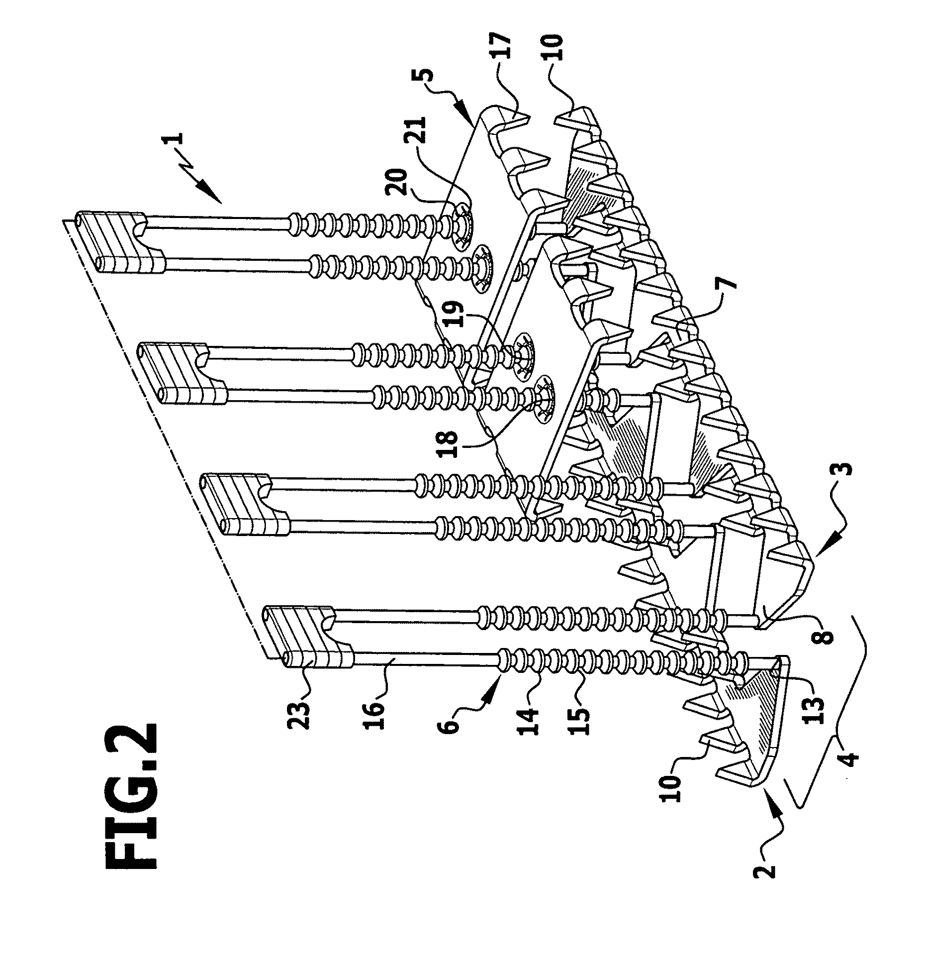
[0033]The sternum closure device 1 illustrated in FIGS. 1 to 3 comprises an inner contact element 4 consisting of two parts 2, 3, a number of outer contact elements 5 as well as snap-in pins 6 secured to the parts 2, 3 of the inner contact element 4. The two parts 2, 3 of the inner contact element 4 are of the same construction; for this reason, only one of the two will be described in detail in the following. The part 2 has an elongated, plate-like and flat web 7, from which triangular connecting areas 8 project to one side and are arranged at a distance to one another in longitudinal direction of the web 7. Pointed projections 10, which are bent upwards and serve to fix the parts 2, 3 on the inner surface of a sternum portion 11 and 12, respectively, project at right angles to the surface of the web 7 between the connecting areas 8, on the one hand, and on the oppositely located longitudinal side 9 of the web 7, on the other hand, which faces away from the connecting areas 8.

[0034...


PUM

PropertyMeasurementUnit
Fractionaaaaaaaaaa
Fractionaaaaaaaaaa
Areaaaaaaaaaaa

Abstract

In a sternum closure device for fixing two sternum portions to be connected to one another, comprising an inner contact element for abutment on the inner surface of the sternum, at least one clamping element fixed to this contact element and projecting transversely from it and at least one outer contact element for abutment on the outer side of the sternum which can be clamped against the inner contact element by means of the clamping element guided through the intermediate space between the sternum portions, it is suggested in order to hinder the separation of the sternum as little as possible during any renewed operation that the inner contact element consist of two parts which are separate from one another and each of which is designed to abut on one of the two sternum portions and that connecting means be provided for the releasable connection of the two parts arranged next to one another.

Description

[0001]This application is a continuation of international application number PCT / EP2007 / 007848 filed on Sep. 8, 2007.[0002]The present disclosure relates to the subject matter disclosed in international application number PCT / EP2007 / 007848 of Sep. 8, 2007 and German application number 10 2006 046 424.9 of Sep. 22, 2006, which are incorporated herein by reference in their entirety and for all purposes.BACKGROUND OF THE INVENTION[0003]The invention relates to a sternum closure device for fixing two sternum portions to be connected to one another, comprising an inner contact element for abutment on the inner surface of the sternum, at least one clamping element which is fixed to this contact element and projects transversely from it and at least one outer contact element for abutment on the outer side of the sternum which can be clamped against the inner contact element by means of the clamping element guided through the intermediate space between the sternum portions.[0004]A sternum c...

Claims


Application Information

Patent Timeline
IPC IPC(8): A61B17/68A61B17/03
CPCA61B17/8076A61B17/809A61B17/823A61L31/10C08L27/18
Inventor MORALES, PEDROWEISSHAUPT, DIETERLUTZE, THEODORDWORSCHAK, MANFRED
Owner AESCULAP AG
Learn More