Conveyance apparatus and image forming apparatus

a technology of conveying apparatus and image, which is applied in the direction of printing and other printing apparatus, can solve the problems of paper not being able to sense by any sensing unit, paper jamming next to the paper, and not being able to specify, etc., and achieves the effect of reducing trouble and being convenient for the operator

Active Publication Date: 2009-09-24
CANON KK
View PDF7 Cites 3 Cited by
  • Summary
  • Abstract
  • Description
  • Claims
  • Application Information

AI Technical Summary

Benefits of technology

[0008]Accordingly, the present invention seeks to solve at least one problem among these and other problems. For example, even in the case of a conveyance apparatus in which paper is partially exposed to the exterior of the apparatus and the direction of paper conveyance is reversed, the present invention makes it possible to suppress trouble along the conveyance path while jamming can be dealt with in a manner convenient for the operator. Other features will be understood from a reading of the entire specification.

Problems solved by technology

If conveyance is allowed to continue with the paper left jammed inside the apparatus, the next sheet of paper also will experience jamming.
However, in a conveyance apparatus in which the paper is partially exposed to the exterior of the apparatus and the direction of paper conveyance is reversed, a state in which the paper cannot be sensed by any sensing unit arises.
In this case, it may not be possible to specify where the paper is situated even if jamming of the paper in the paper conveyance apparatus has been sensed, and therefore it may not be possible to indicate the proper paper removal method to the user.
Since it takes time for the temperature of the fixing device to recover, downtime during which printing cannot be executed results.
Further, if jammed paper is not removed properly, jamming is worsened by succeeding sheets of paper and the apparatus may malfunction.

Method used


Image

  • Conveyance apparatus and image forming apparatus
  • Conveyance apparatus and image forming apparatus
  • Conveyance apparatus and image forming apparatus

Examples


Embodiment Construction

[0022]Embodiments of the present invention will be illustrated below. The individual embodiments described below will be useful in order to understand various concepts of the present invention, such as broader, intermediate and narrower concepts thereof. Further, the technical scope of the present invention is determined by the scope of the claims and is not limited by the individual embodiments set forth below.

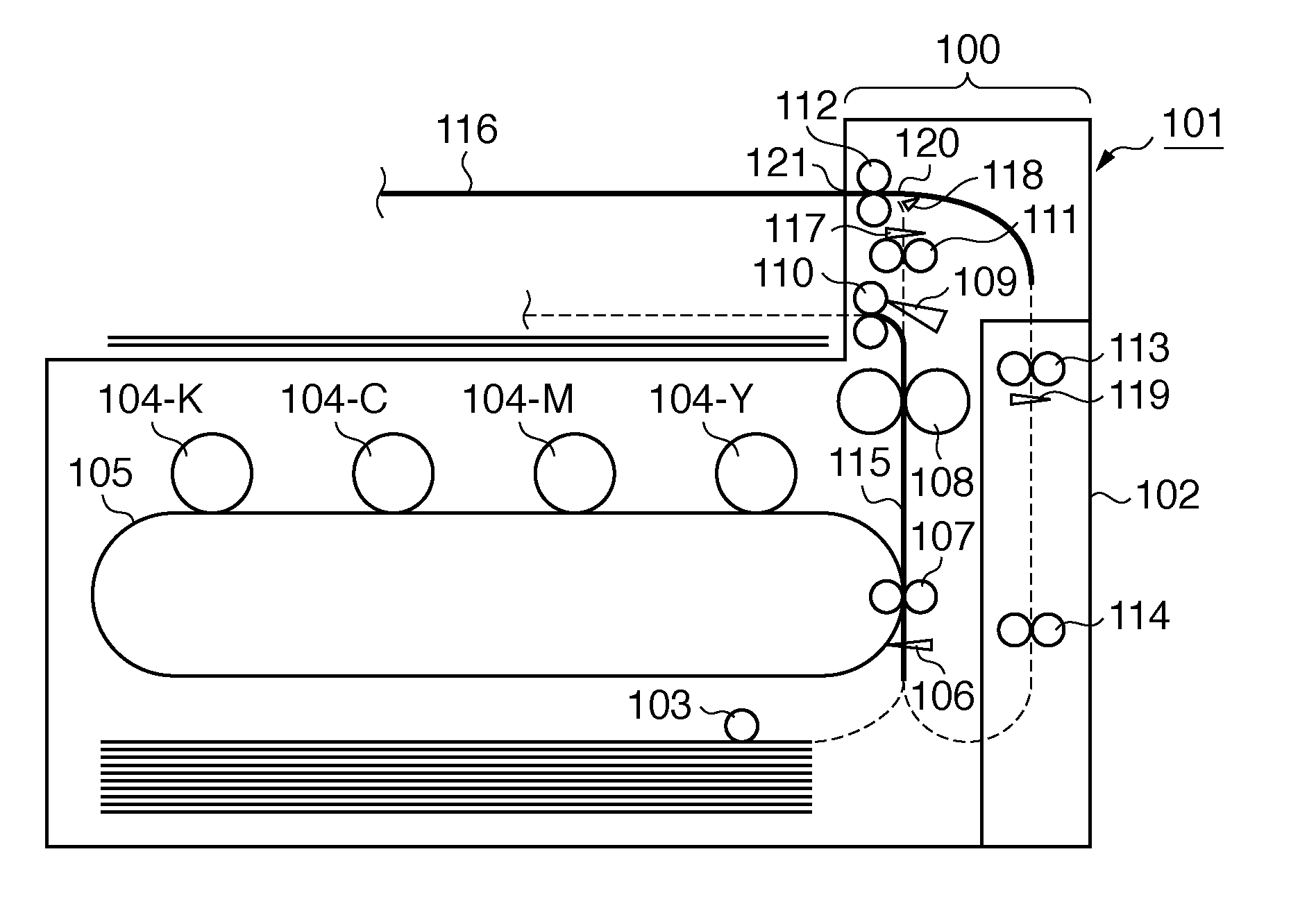
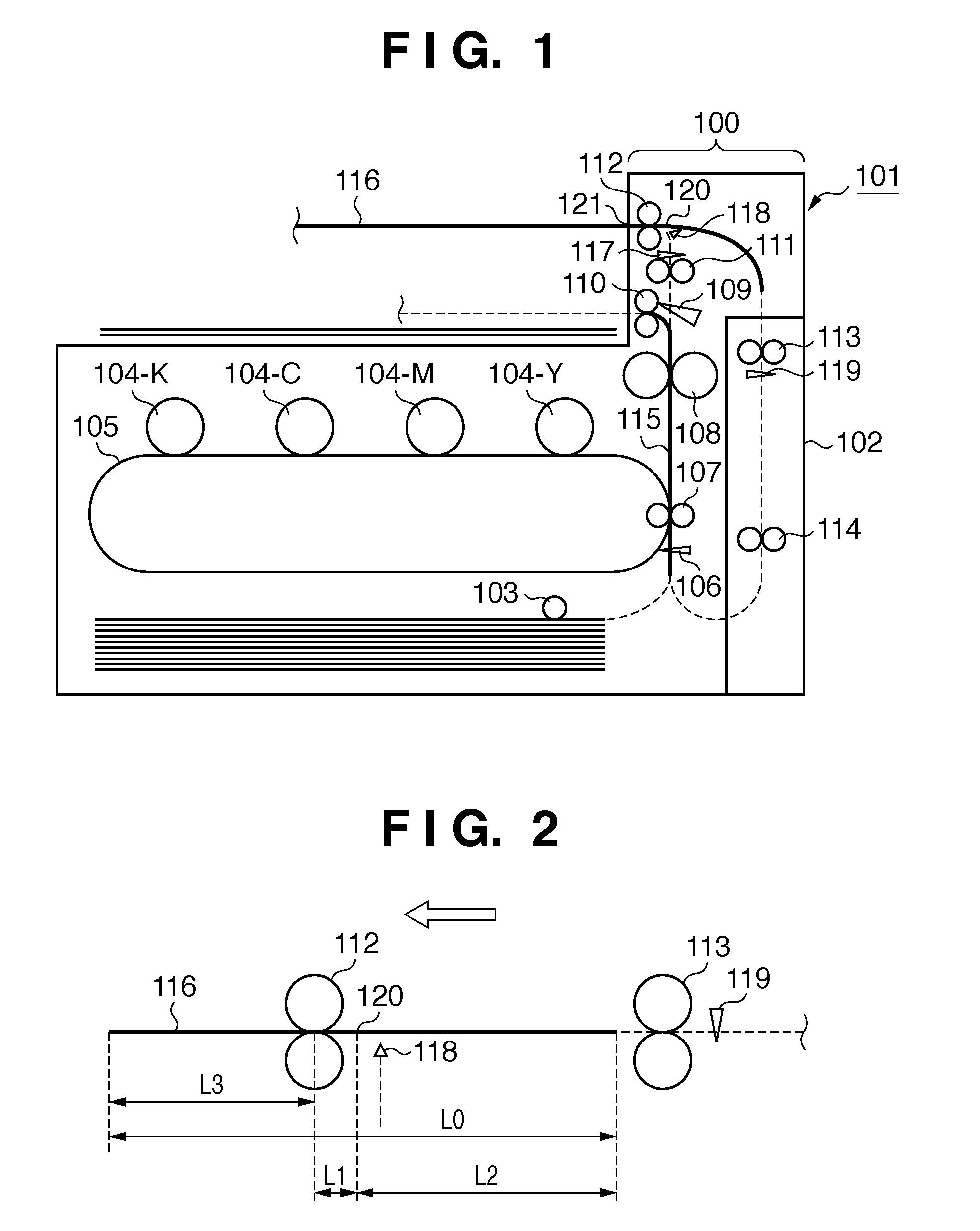
[0023]FIG. 1 is a schematic structural view of a multicolor image forming apparatus 101 that employs a paper conveyance apparatus 100 according to an embodiment of the present invention. The image forming apparatus 101 is an electrophotographic printer. It should be noted that so long as the apparatus is one that employs a conveyance apparatus that partially exposes paper to the exterior and reverses the direction of paper conveyance, the present invention is applicable. The present invention may therefore be applied to equipment other than an image forming apparatus. Further...


PUM


Abstract

Described is a conveyance apparatus that includes a first conveyance path along which a printing medium is conveyed, a first discharge port, and a second conveyance path which causes reversal of the conveyance direction of the printing medium partially exposed from the discharge port and feeds the printing medium to the first conveyance path again. The apparatus further includes an estimation unit which estimates amount of exposure of the printing medium at the discharge port, a decision unit which, when jamming of the printing medium occurs, decides a printing-medium removal method in accordance with the amount of exposure estimated, and an output unit which outputs the removal method decided.

Description

BACKGROUND OF THE INVENTION[0001]1. Field of the Invention[0002]The present invention relates to a conveyance apparatus for conveying a printing medium and, more particularly, to processing of a printing medium that remains retained within a conveyance apparatus in the process of being conveyed through the apparatus.[0003]2. Description of the Related Art[0004]In a conveyance apparatus for conveying paper, paper jam, which is a phenomenon in which the paper is not conveyed properly and remains retained in the conveyance path, occurs. If conveyance is allowed to continue with the paper left jammed inside the apparatus, the next sheet of paper also will experience jamming. The jammed sheet of paper, therefore, must be removed. In addition, it is required that the occurrence of paper jam be sensed accurately.[0005]The specification of Japanese Patent Laid-Open No. 8-245062 proposes a method of sensing the position of jammed paper by placing a number of sensing units, which sense whethe...

Claims


Application Information

Patent Timeline
Patent Type & Authority Applications(United States)
IPC IPC(8): B41J29/393B41J2/01
CPCB41J29/38B41J13/0045
Inventor ENOMOTO, HISASHI
Owner CANON KK
Why Eureka
Try Eureka