Filament lamp

a technology of filament lamps and filament tubes, applied in the field of filament lamps, can solve the problems of blockage of emitted light, difficult to uniformly distribute temperature, and exert a highly adverse influence on the uniformity of temperature distribution of the article to be treated, etc., and achieve the effect of shielding emitted ligh

Inactive Publication Date: 2009-10-01
USHIO DENKI KK
View PDF4 Cites 5 Cited by
  • Summary
  • Abstract
  • Description
  • Claims
  • Application Information

AI Technical Summary

Benefits of technology

[0018]Since the filament lamp according to the present invention is configured so that the internal leads for the filaments disposed in the proximity of the hermetically sealed parts at both ends are supported by the same hermetically sealed parts, the number of internal leads extending into proximity with the filament disposed in the center can be reduced, and the shielding of emitted light caused by insulating tubes fitted onto the internal leads can be reduced, which confers a benefit. As a result, the light emitted from the filament disposed directly above the treated article to be treated can uniformly irradiate the article to be treated.

Problems solved by technology

Accordingly, the light emitted from the filaments sometimes is blocked by the insulating tubes, causing the illumination distribution on the irradiated surface of the article to be treated to not be uniform, and thus, making it impossible to make the temperature distribution uniform, which is problematic.
Blockage of the emitted light from the central filament, disposed directly above the center of the article to be treated, exerts a highly adverse impact on the uniformity of temperature distribution on the article to be treated.
The foregoing description cited an example of fitting insulating tubes onto the internal leads, but even in a case in which no insulating tubes are present, the same problem of blockage of emitted light occurs.

Method used


Image

  • Filament lamp
  • Filament lamp
  • Filament lamp

Examples


Embodiment Construction

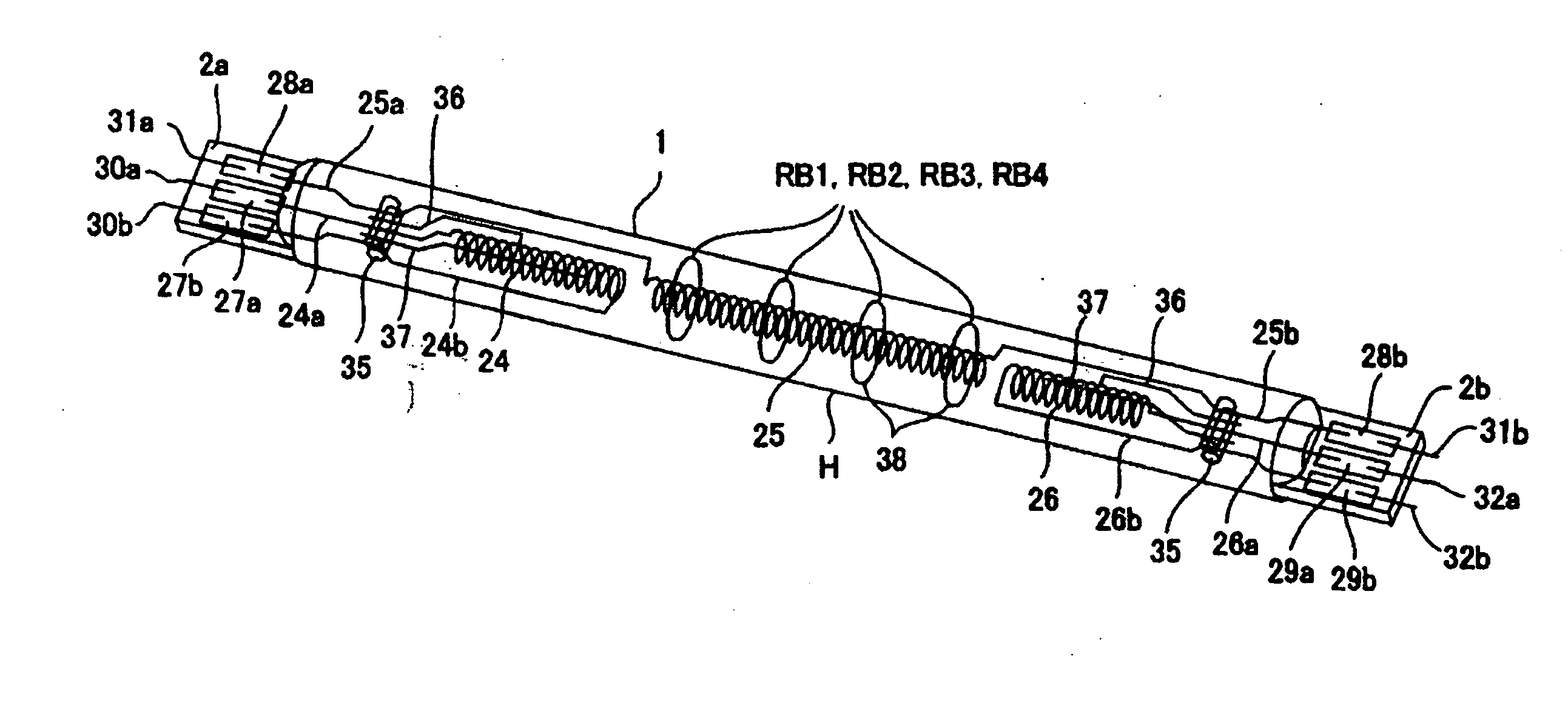
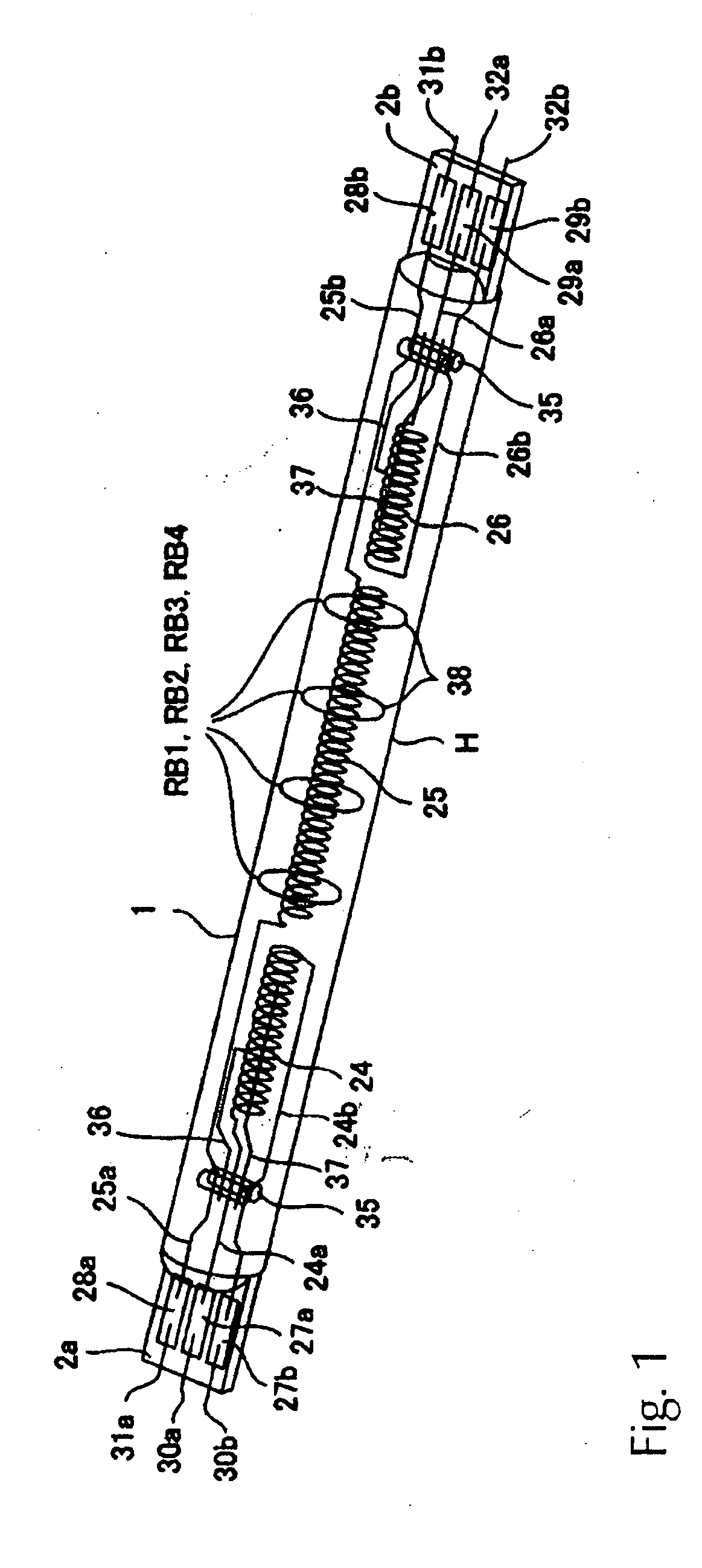
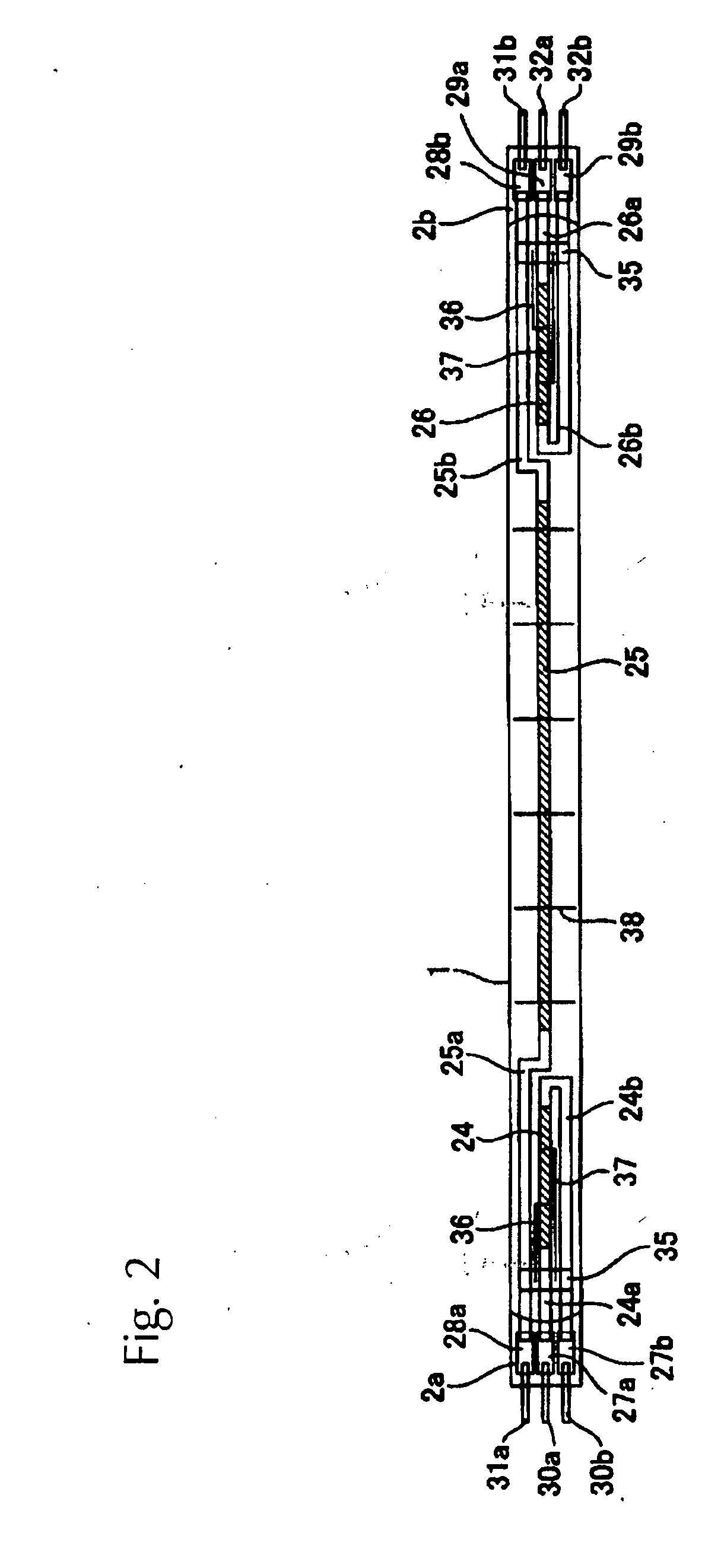
[0024]FIGS. 1 & 2 show the overall configuration of the filament lamp according to a first embodiment of the present invention.

[0025]Three filaments 24, 25, 26 are disposed together inside a light-emitting tube 1 extending in the tube axis direction thereof. Internal leads 24a, 24b for the filament 24, proximate to a hermetically sealed part 2a at one end, are connected to the respective ends of the filament 24 extending from the hermetically sealed part 2a. These internal leads 24a, 24b are both supported so as to connect with a respective metal foil 27a, 27b in the same hermetically sealed part 2a.

[0026]At the same time, the internal leads 25a, 25b on the filament 25 disposed at the center extend to the hermetically sealed parts 2a, 2b and are supported so as to connect with metal foils 28a, 28b, respectively, in the hermetically sealed parts 2a, 2b at each end.

[0027]Regarding the filament 26 proximate to the hermetically sealed part 2b at the other end, as with filament 24 descr...


PUM


Abstract

To provide a filament lamp having a plurality of filaments disposed in sequence in the axial direction of a light-emitting lamp tube which is configured so as not to shield emitted light from a center filament, internal leads for two filaments disposed proximate hermetically sealed parts at both ends are connected to metal foils in the same hermetically sealed part.

Description

BACKGROUND OF THE INVENTION[0001]1. Field of Invention[0002]The present invention relates to a filament lamp, and in particular, to a filament lamp used to heat an article to be treated.[0003]2. Description of Related Art[0004]Heat treatment devices capable of heating an article to be treated without making contact by optical irradiation from an incandescent lamp or other light source in which filaments are disposed inside a light-emitting tube composed of optically transparent material, for example, are widely used as heat treatment devices in rapid thermal processing (RPT) employed during the film formation, oxidation, impurity dispersion, nitriding, film stabilization, silicidation, crystallization, and ion implantation processes that are part of the semiconductor manufacturing process (see Japanese Unexamined Patent Application JP 7-37833 and Japanese Unexamined Patent Application JP 2002-203804).[0005]One of the present inventors, with others, has proposed a filament lamp havin...

Claims


Application Information

Patent Timeline
Patent Type & Authority Applications(United States)
IPC IPC(8): H01J7/44
CPCH01K1/40H01K9/08H01K7/00
Inventor TANINO, KENJITANIGUCHI, SHINJIUESHIMA, YUKIO
Owner USHIO DENKI KK
Why Eureka
Try Eureka