Minimizing Electromagnetic Interference in Coil Transducers

a technology of coil transducer and electromagnetic interference, which is applied in the direction of transformer/react mounting/support/suspension, baseband system details, magnetic bodies, etc., can solve the problems of capacitive devices typically showing poor high voltage hold-off or breakdown, operation and design constraints, etc., to minimize the pick-up of electromagnetic interference

Active Publication Date: 2009-10-01
AVAGO TECH INT SALES PTE LTD
View PDF89 Cites 61 Cited by
  • Summary
  • Abstract
  • Description
  • Claims
  • Application Information

AI Technical Summary

Benefits of technology

[0008]In one embodiment, there is provided a coil transducer system comprising a coil transducer comprising a generally planar substrate comprising opposing upper and lower surfaces and including therein a dielectric barrier, the dielectric barrier comprising an electrically insulating, non-metallic, non-semiconductor, low-dielectric-loss material, a first electrically conductive coil disposed above the upper surface of the substrate, the first coil extending between first and second coil input terminals disposed at opposite ends thereof, a second electrically conductive coil disposed below the lower surface of the substrate, the second coil extending between first and second output coil terminals disposed at opposite ends thereof, and a transmitter circuit comprising first and second transmitter output terminals; wherein a first wire is electrically connected to, and extends between, the first transmitter output terminal and the first input coil terminal, a second wire is electrically connected to, and extends between, the second transmitter output terminal and the second input coil terminal, the first and second wires are substantially parallel to one another or exhibit substantially similar angles respecting a major axis of the coil transducer, the first and second wires have substantially a same first length, the first and second wires thereby being configured to minimize the pick-up of electromagnetic interference (“EMI”) thereby.

Problems solved by technology

Prior art optical devices typically achieve high voltage isolation by employing LEDs and corresponding photodiodes to transmit and receive light signals, usually require high power levels, and suffer from operational and design constraints when multiple communication channels are required.
Prior art magnetic devices typically achieve high voltage isolation by employing opposing inductively-coupled coils, usually require high power levels (especially when high data rates are required), typically require the use of at least three separate integrated circuits or chips, and often are susceptible to electromagnetic interference (“EMI”).
Such capacitive devices typically exhibit poor high voltage hold-off or breakdown characteristics
The design of small high speed galvanic isolators or coil transducers presents several formidable technical challenges, such as how to handle EMI, large-magnitude fast transients, and other forms of electrical noise while maintaining high voltage breakdown characteristics, and acceptable data or power transfer rates.
In some types of isolators, however, signal transmission can be disrupted in environments containing considerable amounts of EMI.

Method used


Image

  • Minimizing Electromagnetic Interference in Coil Transducers
  • Minimizing Electromagnetic Interference in Coil Transducers
  • Minimizing Electromagnetic Interference in Coil Transducers

Examples


Embodiment Construction

[0022]In the following description, specific details are provided to impart a thorough understanding of the various embodiments of the invention. Upon having read and understood the specification, claims and drawings hereof, however, those skilled in the art will understand that some embodiments of the invention may be practiced without hewing to some of the specific details set forth herein. Moreover, to avoid obscuring the invention, some well known circuits, materials and methods finding application in the various embodiments of the invention are not disclosed in detail herein.

[0023]In the drawings, some, but not all, possible embodiments of the invention are illustrated, and further may not be shown to scale.

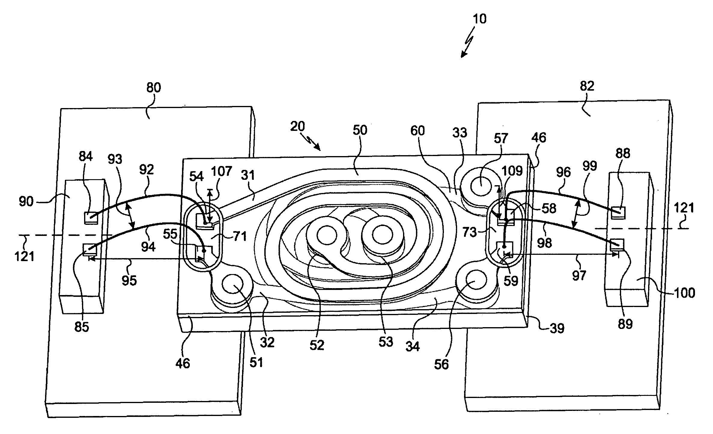
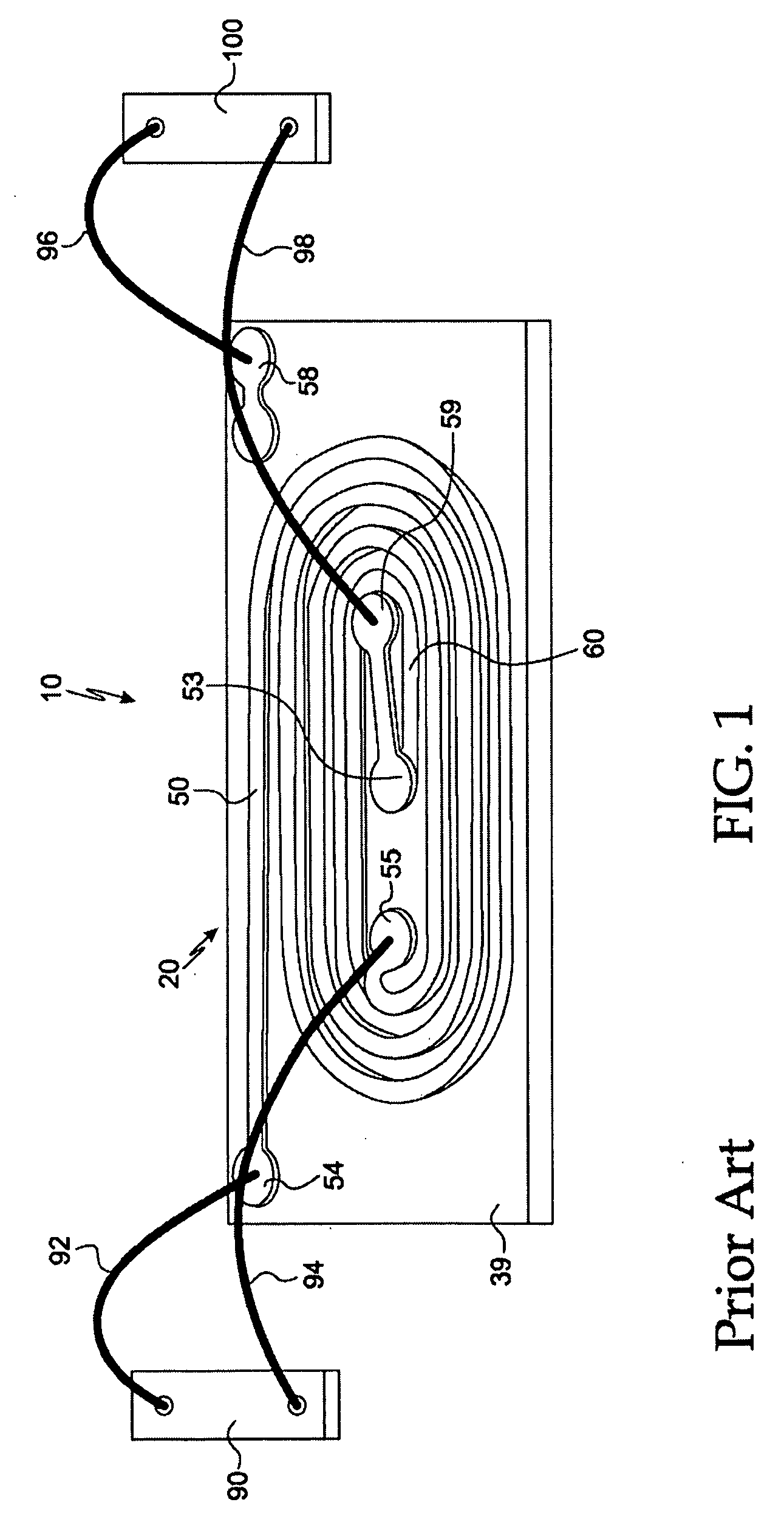
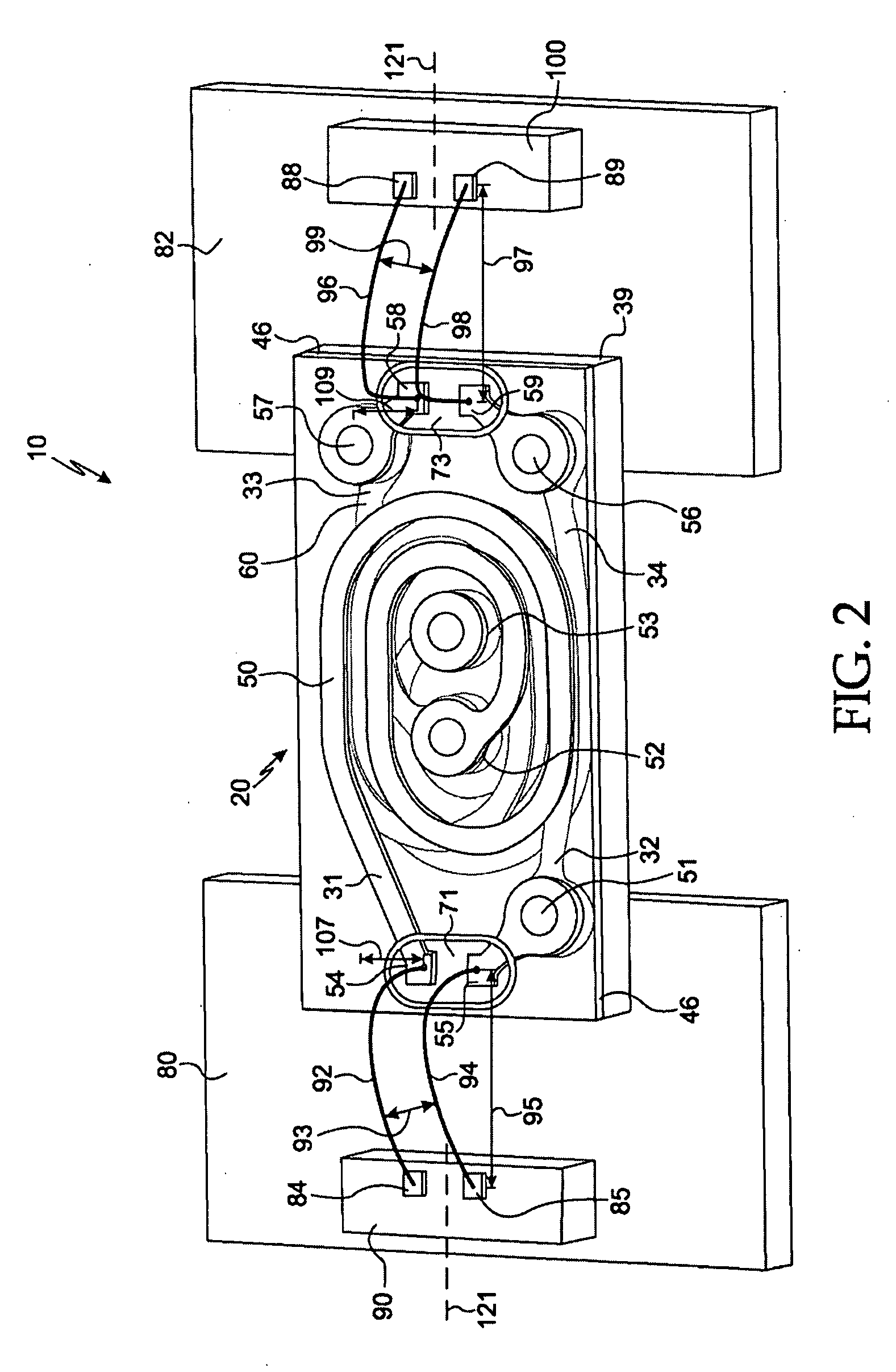
[0024]The term “horizontal” as used herein is defined as a plane substantially parallel to the conventional plane or surface of the substrate of the invention, regardless of its actual orientation in space. The term “vertical refers to a direction substantially perpendicular...


PUM

PropertyMeasurementUnit
angleaaaaaaaaaa
anglesaaaaaaaaaa
anglesaaaaaaaaaa

Abstract

Disclosed herein are various embodiments of means and methods for reducing the pick-up of electromagnetic interference (“EMI”) by coil transducers configured to provide high voltage isolation and high voltage breakdown performance characteristics in small packages. In some embodiments, the lengths, heights, and horizontal distances between wires electrically connecting transmitter circuits and receiver circuits to coil transducers are minimized and optimized respecting one another.

Description

RELATED APPLICATIONS[0001]This application claims priority and other benefits from, and is a continuation-in-part of: (a) U.S. patent application Ser. No. 12 / 059,979 filed Mar. 31, 2008 entitled “Galvanic Isolators and Coil Transducers” to Fouquet et al. (hereafter “the '979 patent application”); (b) U.S. patent application Ser. No. 12 / 059,747 filed Mar. 31, 2008 entitled “Coil Transducer with Reduced Arcing and Improved High Voltage Breakdown Performance Characteristics” to Fouquet et al. (hereafter “the '747 patent application”), and (c) U.S. patent application Ser. No. 12 / 370,208 filed Feb. 12, 2009 entitled “High Voltage Hold-off Coil Transducer” to Fouquet et al. (hereafter “the '208 patent application”). This application also hereby incorporates by reference herein in their respective entireties the foregoing '979, '747 and '208 patent applications.FIELD OF THE INVENTION[0002]Various embodiments of the invention described herein relate to the field of data signal and power tra...

Claims


Application Information

Patent Timeline
Patent Type & Authority Applications(United States)
IPC IPC(8): H01F5/00H01F7/06
CPCH01F17/0006Y10T29/49071H01F19/08H01F27/2804H01F27/34H01F27/40H01F2019/085H01F2038/143H03F3/45192H03F3/45475H03F2203/45008H03F2203/45101H03F2203/45586H04B5/0093H04L25/0266H01L2224/48091H01F17/0013Y10T29/4902Y10T29/49073H01L2224/73265H01L2224/49111H01L2224/48195H01L2924/30107H01L2924/3025H01L2924/00014H01L2924/00
Inventor FOUQUET, JULIE E.TROTT, GARY R.BAUMGARTNER, RICHARD
Owner AVAGO TECH INT SALES PTE LTD
Why Eureka
Try Eureka