Printer

a printing machine and printing plate technology, applied in the field of printing machines, can solve the problems of degrading affecting the quality of the printing medium, slowing down or stopping the feed of the print medium, etc., and achieve the effect of preventing the printing medium from being wrinkled and extended, and improving the drying property of the ink

Inactive Publication Date: 2009-10-01
SEIKO PRECISION CO LTD
View PDF1 Cites 8 Cited by
  • Summary
  • Abstract
  • Description
  • Claims
  • Application Information

AI Technical Summary

Benefits of technology

[0013]It is therefore an object of the present invention to provided a printer in which a quality of a print medium can be maintained independently of a change in feeding speed of the print medium and in which a drying capability of ink is improved, and to provided a printer in which the workability is improved.
[0015]With such a configuration, since the blowing amount changing portion can be controlled in response to the feeding speed of the print medium, the temperature of hot air is set high beforehand and the blowing amount is changed, even when the feeding speed of the print medium is reduced by any cause, the print medium is prevented from being wrinkled and extended, and the drying property of the ink is improved.

Problems solved by technology

For example, when the production line is slowed down or stopped by a trouble with equipment thereof, the feed of the print medium is also slowed down or stopped.
For example, in a case where the feed of the print medium is stopped, the drying heater blows hot air to a certain portion of the print medium over a long time.
When hot air is blown to the certain portion of the print medium with over a long time, the print medium may be heated excessively, so that the print medium will be wrinkled and extended.
This degrades the quality of the print medium.
However, in a case where the temperature of hot air is set to be low, for example, when the feeding speed of the print medium is increased, the drying of the ink applied on the print medium may be insufficient.
Also, this may produce smear caused by transfer.
This may lead to the fan heated enough to brake a mechanical part such as a bearing.
This causes the air to be heated, and the fan is excessively heated by the heated air.
In this manner, the mechanism of the fan may be broken.
However, when cooling is needed, there is a drawback in that the temperature is hardly reduced, since the high temperature air is not immediately exhausted.
For this drawback, at the end of work, it is necessary to maintain the rotation of the fan for a long time even after the drying heater is turned off, in order to decrease the temperature of the drying heater.
Consequently, the period from the end of work to the power-off of the whole printer becomes longer, thereby degrading the workability.

Method used


Image

  • Printer
  • Printer
  • Printer

Examples


first embodiment

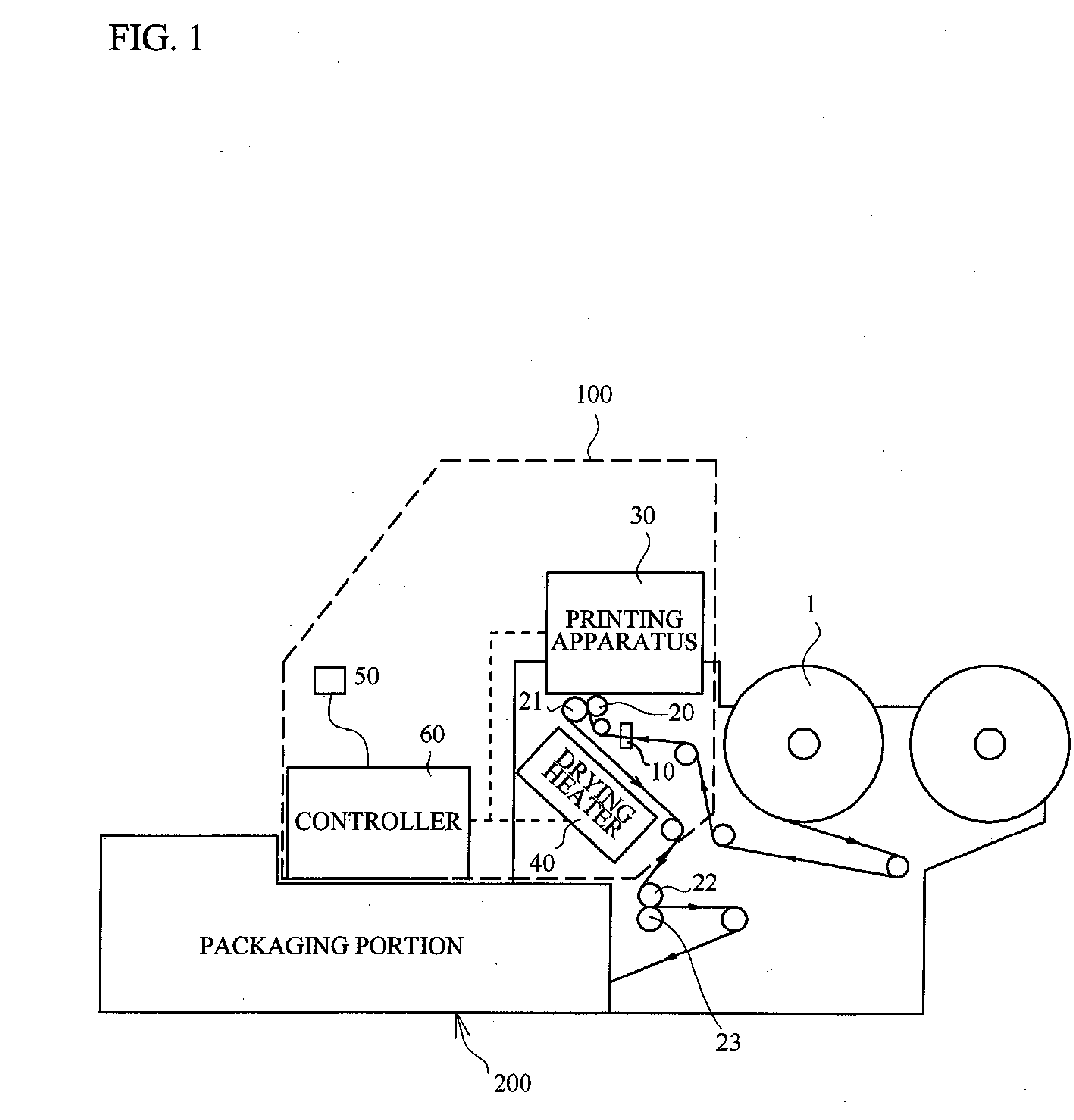
[0030]FIG. 1 is an explanatory view in which a printer according to the present embodiment of the present invention is employed in packaging equipment.

[0031]Referring to FIG. 1, the packaging equipment includes a printer portion 100 and a packaging portion 200.

[0032]The printer portion 100 prints on a packaging medium, as a print medium, for packaging a packaged material (product). For example, a package film 1 as the print medium is printed with a bar-code, a packaging date, or a expiration date, so as to correspond to the packaged product.

[0033]Subsequently, the package film 1 printed by the printer portion 100 packages a predetermined product with the packaging portion 200. The packaged product is, e.g., something to eat.

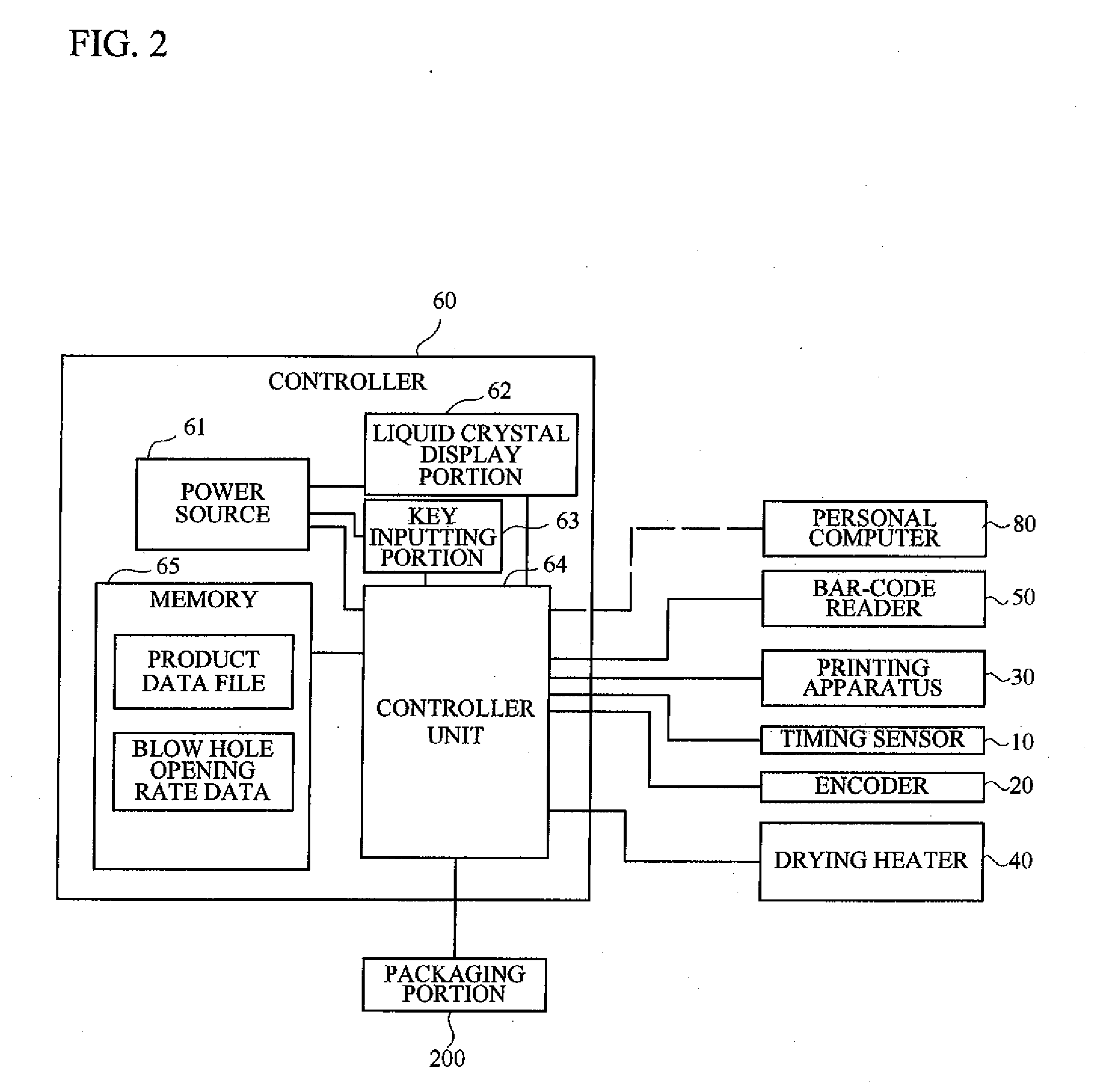
[0034]The printer portion 100 includes a timing sensor 10, an encoder 20, a printing apparatus 30, a drying heater 40 (drying portion), a bar-code reader 50, and a controller 60.

[0035]As illustrated in FIG. 1, the package film 1 packaging the product is rolled, a...

second embodiment

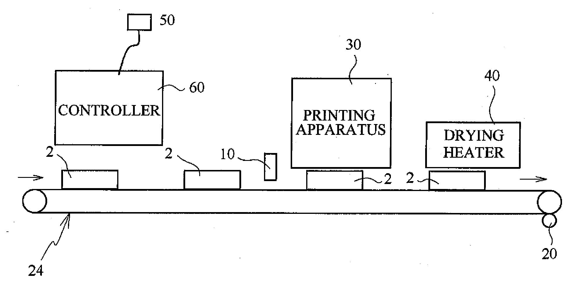
[0091]Next, a description will be given of a case where something is printed on a box by using a printer according to the present invention.

[0092]FIG. 12 is an explanatory view of the case where something is printed on a box by using a printer. Additionally, the same components as those of the first embodiment are denoted by the same reference numerals as those of the first embodiment in order to avoid a duplicated explanation.

[0093]A box 2, as a printed medium, is fed in a given direction by the driving roller 22. The timing sensor 10, the printing apparatus 30 and the drying heater 40, facing the box 2, are arranged in this order from an upstream side to a downstream side. The box 2 fed by the driving roller 22 is read out by the timing sensor 10 to measure the print timing. The encoder 20 is arranged to be rotated in accordance with the movement of the belt conveyor 23. The speed of the belt conveyor 23 is detected by the encoder 20, thereby detecting the feeding speed of the box...


PUM


Abstract

A printer includes: a print head for ejecting ink on a print medium; a drying portion for blowing hot air to the printed print medium so as to expedite drying of the ink applied on the printed print medium, the drying portion including a blowing amount changing portion changeable a blowing amount of the hot air blown to the print medium; a detecting portion for detecting a feeding speed of the print medium; and a controller unit for controlling the blowing amount changing portion in response to the feeding speed of the print medium detected by the detecting portion.

Description

CROSS-REFERENCE TO RELATED APPLICATION[0001]This application is a continuation of and claims priority to International Patent Application No. PCT / JP2007 / 072939 filed on Nov. 28, 2007, which claims priority to Japanese Patent Application No. 2006-333228 filed on Dec. 11, 2006, subject matter of these patent documents is incorporated by reference herein in its entirety.BACKGROUND OF THE INVENTION[0002]1. Field of the Invention[0003]The present invention relates to a printer.[0004]2. Description of the Related Art[0005]Conventionally, there has been known a printer which includes a drying heater. The drying heater blows hot air to a print medium printed so as to dry ink applied on the print medium (see Japanese patent application publication No. 2005-241263). Such a drying heater is arranged to blow hot air to the print medium in the partway of a career of the print medium. The drying heater promotes to reduce a drying period of the ink.[0006]In such a printer, there is a case where a ...

Claims


Application Information

Patent Timeline
Patent Type & Authority Applications(United States)
IPC IPC(8): B41J29/38B41J2/01
CPCB41J29/02B41J11/002B41J11/0022B41J2/07B41J29/38
Inventor NAKAGAKI, YUJI
Owner SEIKO PRECISION CO LTD
Why Eureka
Try Eureka