Liquid container and membrane valve

a liquid container and membrane valve technology, applied in the direction of diaphragm valves, functional valve types, engine diaphragms, etc., can solve the problems of negative pressure generated by the valve becoming unstable, valve opening and closing becoming unstable, etc., to reduce the possibility of coil spring contacting and reduce the possibility of unintentional adherence

Inactive Publication Date: 2009-10-01
SEIKO EPSON CORP
View PDF15 Cites 19 Cited by
  • Summary
  • Abstract
  • Description
  • Claims
  • Application Information

AI Technical Summary

Benefits of technology

[0008]The advantage of a number of modes of the invention is the provision of technology that decreases the possibility of problems relating to valves with liquid containers installed in a liquid jetting device.
[0011]By working in this way, the membrane valve is formed using an elastomer, so the deformation of the membrane portion of the membrane valve in relation to the pressure is stabilized, and the negative pressure generated by the membrane valve is stabilized.
[0013]With this constitution, the position of the membrane valve is determined by the N (N is an integer of 2 or greater) engaging portions, so it is possible to reduce the possibility of movable seal position skew.
[0015]With this constitution, when the seal portion is deformed, it is possible to reduce the possibility of the membrane portion deforming to an unintentional shape.
[0017]With this constitution, it is possible to reduce the possibility of deformation of the membrane portion when the membrane valve is placed on a plane.
[0019]With this constitution, when the coil spring is moved within the concave portion, it is possible to reduce the possibility of the coil spring contacting the projecting portion. Therefore, it is possible to reduce the possibility of unintentional adherence of the coil spring and the projecting portion.

Problems solved by technology

However, there is also the possibility of various problems relating to valves.
Examples of problems include the possibility of the negative pressure generated by the valve becoming unstable, and the possibility of the valve opening and closing becoming unstable, and the differential pressure control becoming unstable.
These kinds of problems are not limited to the ink tank of an inkjet printer, but are also problems common to liquid containers that can be installed on a liquid jetting device.

Method used


Image

  • Liquid container and membrane valve
  • Liquid container and membrane valve
  • Liquid container and membrane valve

Examples


first embodiment

A. First Embodiment

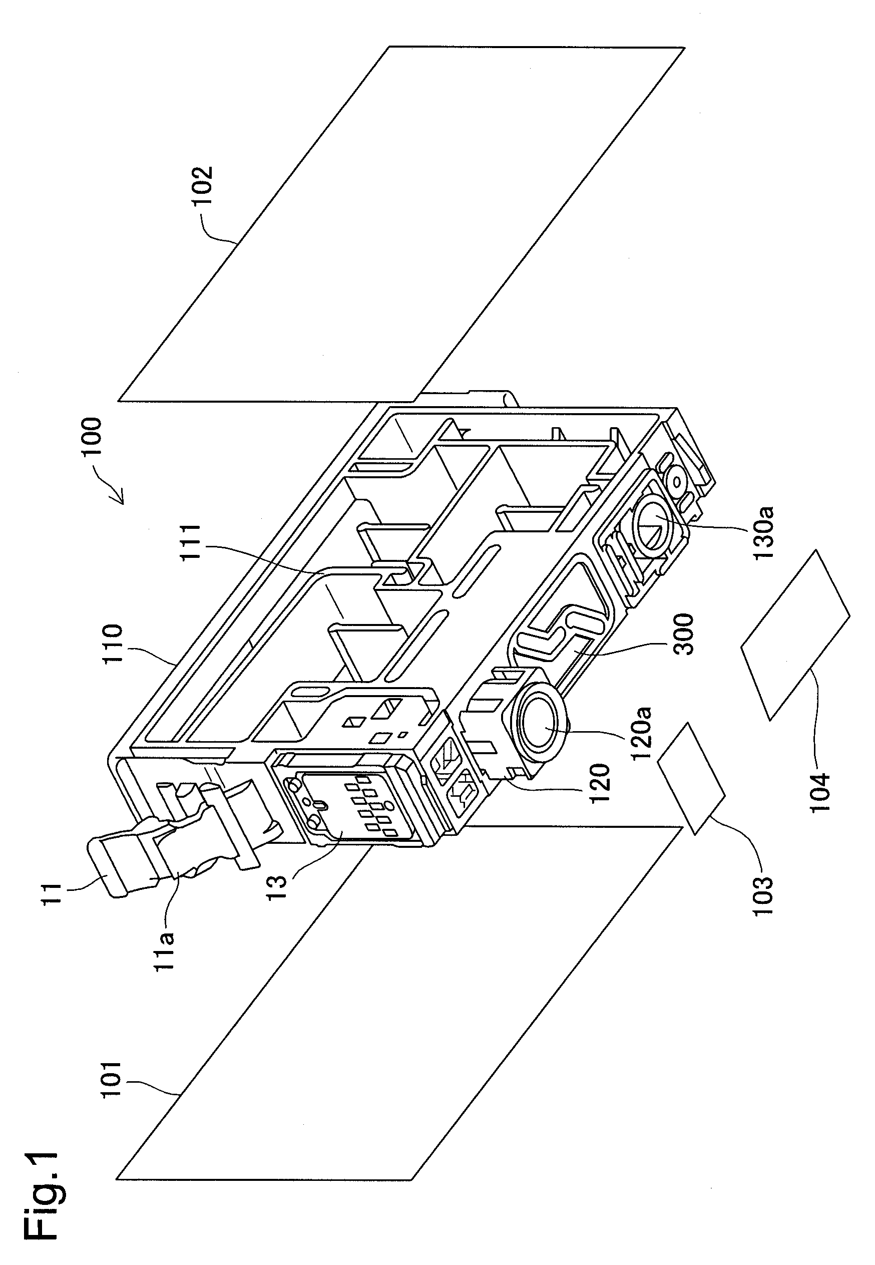
[0061]FIG. 1 is an exploded perspective view of an ink cartridge as the first embodiment of the invention. The ink cartridge 100 is equipped with a main body 110, a first side film 101, a second side film 102, a first bottom film 103, and a second bottom film 104.

[0062]Provided on the bottom surface of the main body 110 is an ink supply section 120 which has a supply port 120a for supplying ink to an inkjet printer. At the bottom surface of the main body 110 is opened an air opening hole 130a for introducing the atmosphere inside the ink cartridge 100. A spring seat member 300 is fit on the bottom surface of the main body 110. An engaging lever 11 is provided on the front surface of the main body 110. A projection 11a is formed on the engaging lever 11. A circuit board 13 is provided on the lower side of the engaging lever 11 of the front of the ink cartridge 100. A plurality of electrode terminals are formed on the circuit board 13, and when installing in a liqui...

second embodiment

B. Second Embodiment

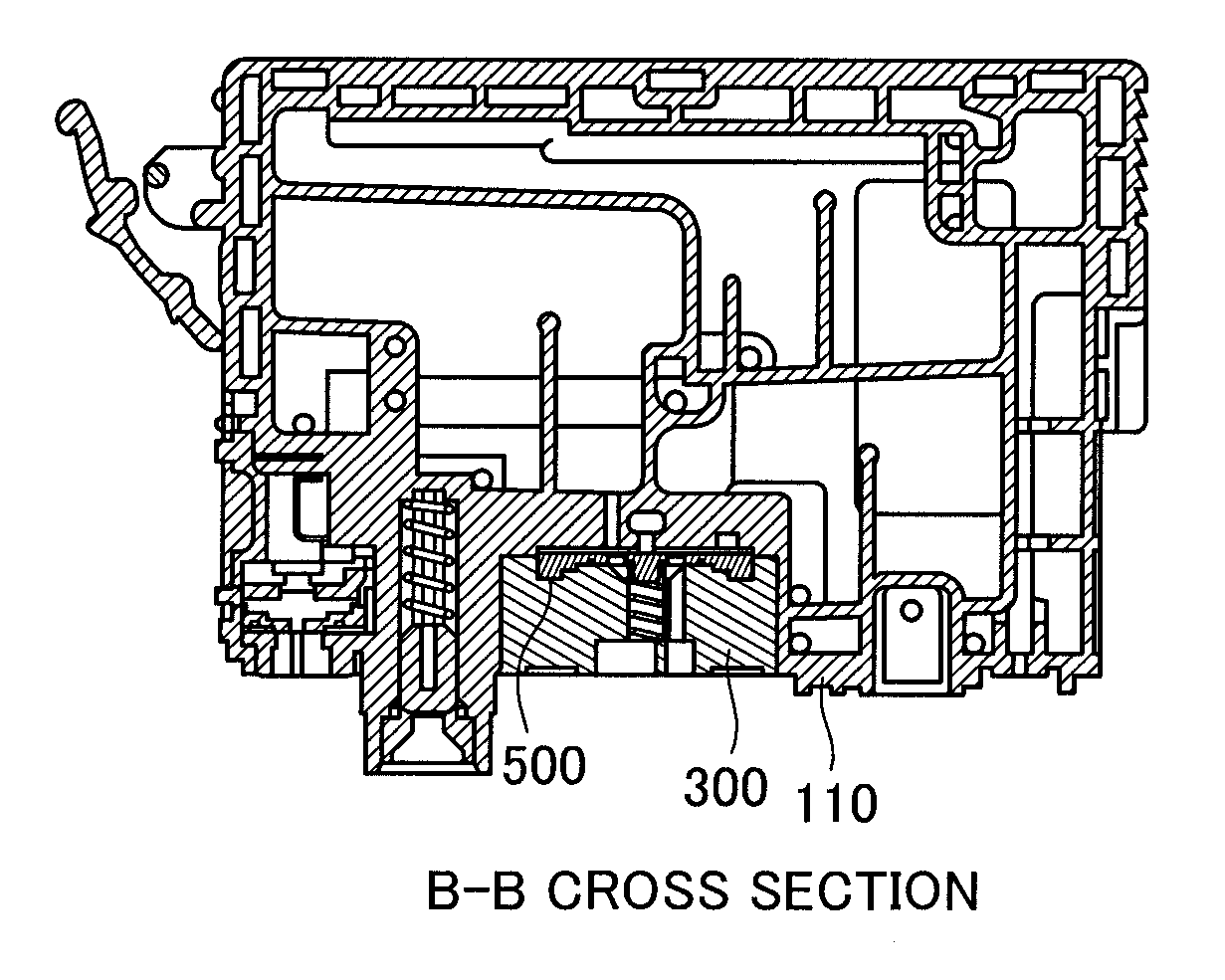
[0081]FIG. 9 is a drawing for describing the constitution of the valve section 180 of the second embodiment. With the membrane portion 510b of the second embodiment, in contrast to the membrane portion 510b of the first embodiment, this is formed diagonally rather than horizontally in the closed valve state of the membrane valve 500. Specifically, 510b of the second embodiment has an incline that is lower the more it faces the center of the membrane valve 500, and higher the more it faces the outside of the membrane valve 500. As a result, the fluid of the upstream valve chamber 181 is gathered near the contact area, so ink does not easily remain in the upstream valve chamber 181. As a result, the ink volume that remains inside the ink cartridge 100 is suppressed, and it is possible to supply a larger volume of ink to the inkjet printer.

third embodiment

C. Third Embodiment

[0082]FIG. 10 is a drawing for describing the constitution of the valve section 180 of the third embodiment. There is no coil spring 400 in the valve section 180 of the third embodiment. With the membrane valve 500 of the third embodiment, the axis portion 550c is extended along the lower side, and reaches the spring supporting portion 320. Specifically, the cylindrical part of the bottom of the axis portion 550 functions in place of the coil spring 400 as an urging member that urges the membrane valve 500 to the apex shape 115 side. Working in this way, by making the membrane valve 500 and the urging member a single unit, it is possible to reduce the number of parts.


PUM


Abstract

A membrane valve having a membrane portion is used. The membrane valve can be formed using an elastomer. Also, the membrane valve can include N (N is an integer of 2 or greater) engaging portions that engage with the membrane support portion. Also, the membrane portion can also be affixed at a position closer to the first seal surface than the second seal surface in the seal portion. Here, the contact area of the first seal surface and the first member can be larger than the contact surface of the second seal surface and the second member. Also, in a first case where the end of the projecting portion is faced to a first plane and the membrane valve placed on the first plane, the end of the first support portion contacts the first plane and supports the membrane valve, and the end of the projecting portion can contact the first plane in a state with the membrane portion not deformed. Also, the projecting portion inserted inside the end of the coil spring can be arranged at the center axis side separated from the range of the position in which the projecting portion can contact the end of the coil spring by motion of the coil spring within the concave portion in the direction perpendicular to the center axis of the coil spring.

Description

CROSS-REFERENCE TO RELATED APPLICATIONS[0001]The present application claims the priority based on Japanese Patent Application No. 2008-73272 filed on Mar. 21, 2008, the disclosure of which is hereby incorporated by reference in its entirety.BACKGROUND[0002]1. Technical Field[0003]The present invention relates to a liquid container and a membrane valve, and particularly to a liquid container that can be installed in a liquid jetting device and a membrane valve used for this liquid container.[0004]2. Description of the Related Art[0005]With an ink tank that supplies ink to an inkjet printer, technology is known that keeps the stored ink at negative pressure. For example, as means for generating negative pressure, an ink tank having a valve constitution using a membrane valve and a spring is known.[0006]Also, various technologies that use valves are known relating to ink tanks that supply ink to inkjet printers. For example, valves for introducing the atmosphere to an ink tank are know...

Claims


Application Information

Patent Timeline
Patent Type & Authority Applications(United States)
IPC IPC(8): B41J2/175F16K7/00
CPCB41J2/1752B41J2/18B41J2/17596B41J2/17553
Inventor MIZUTANI, TADAHIROKAWATE, HIROYUKIISHIZAWA, TAKUOYA, SHUN
Owner SEIKO EPSON CORP
Why Eureka
Try Eureka