
Liquid jetting system, liquid container, holder, and liquid jetting apparatus having holder

Active Publication Date: 2009-10-01
SEIKO EPSON CORP
View PDF14 Cites 16 Cited by
  • Summary
  • Abstract
  • Description
  • Claims
  • Application Information

AI Technical Summary

Benefits of technology

[0007]Therefore, it is one object of the present invention to prevent detachment of a liquid container in a liquid container installable in a liquid jetting apparatus and a holder adapted to receive installation of such a liquid container.

Problems solved by technology

However, in conventional designs, there was a risk that when the ink cartridge is installed in the holder, the ink cartridge would sometimes become detached from the holder.
This problem is not one that is limited to ink cartridges and holders used in ink-jet printers, but is a problem common generally to liquid containers installable in liquid devices, and to holders designed to accommodate installation of such liquid containers.

Method used


Image

  • Liquid jetting system, liquid container, holder, and liquid jetting apparatus having holder
  • Liquid jetting system, liquid container, holder, and liquid jetting apparatus having holder
  • Liquid jetting system, liquid container, holder, and liquid jetting apparatus having holder

Examples


embodiment

A. Embodiment

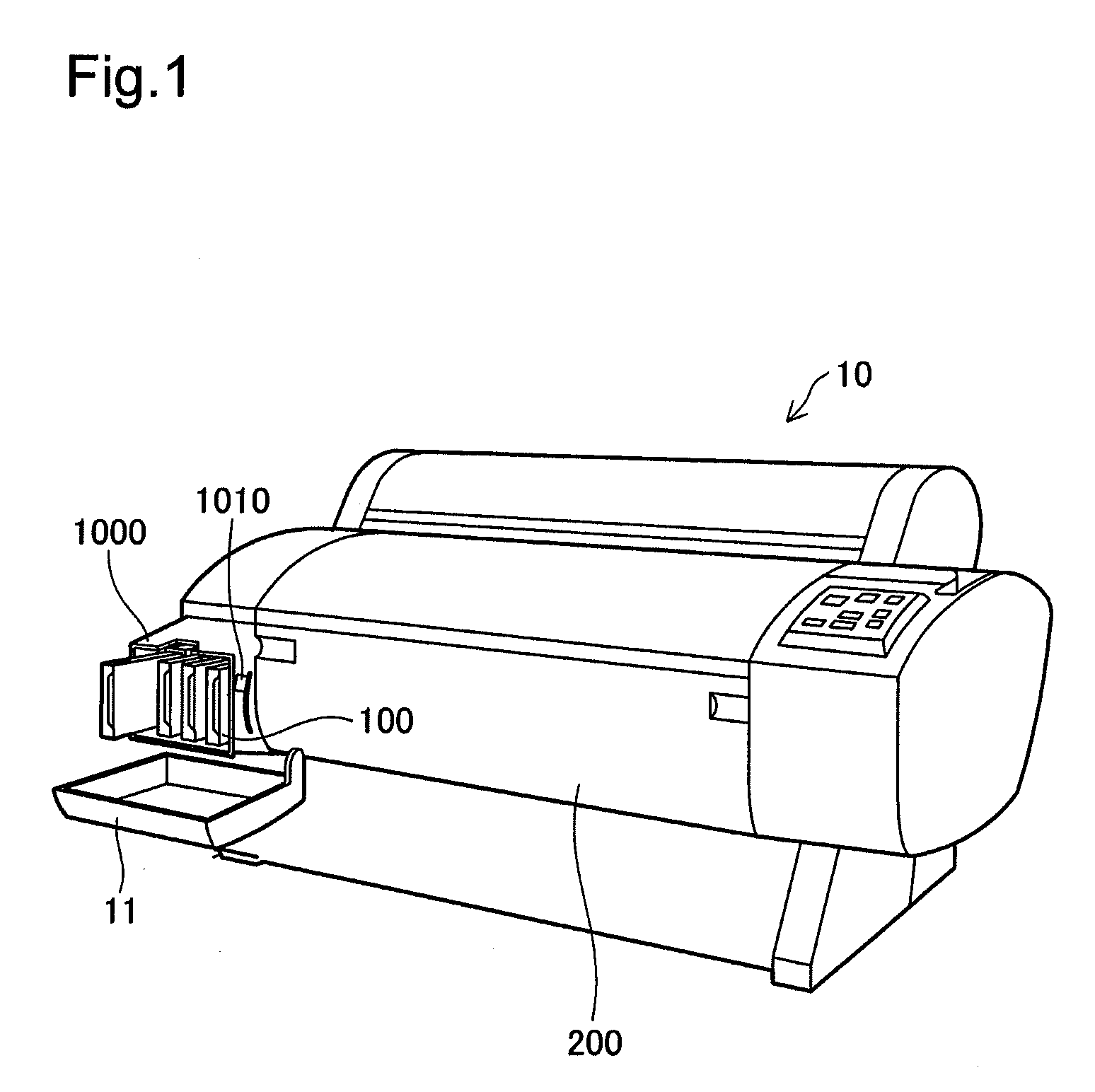
[0056]FIG. 1 is a perspective view of an ink-jet printer as an embodiment of the present invention. This ink-jet printer 10 is furnished with a printer chassis 200, and with a holder 1000 disposed in a section of the printer chassis 200, for receiving installation of ink cartridges. The holder 1000 of the ink-jet printer 10 has a rotatable cover 11. One example of the ink-jet printer 10 would be a large-format ink-jet printer adapted to record large-size paper (e.g. A2 to A0 size) for posters or the like. The holder 1000 houses several ink cartridges 100. The ink cartridges 100, which respectively contain inks of prescribed color, are installed in a row in the holder 1000. The ink-jet printer 10 can thereby carry out full color printing onto the printer paper.

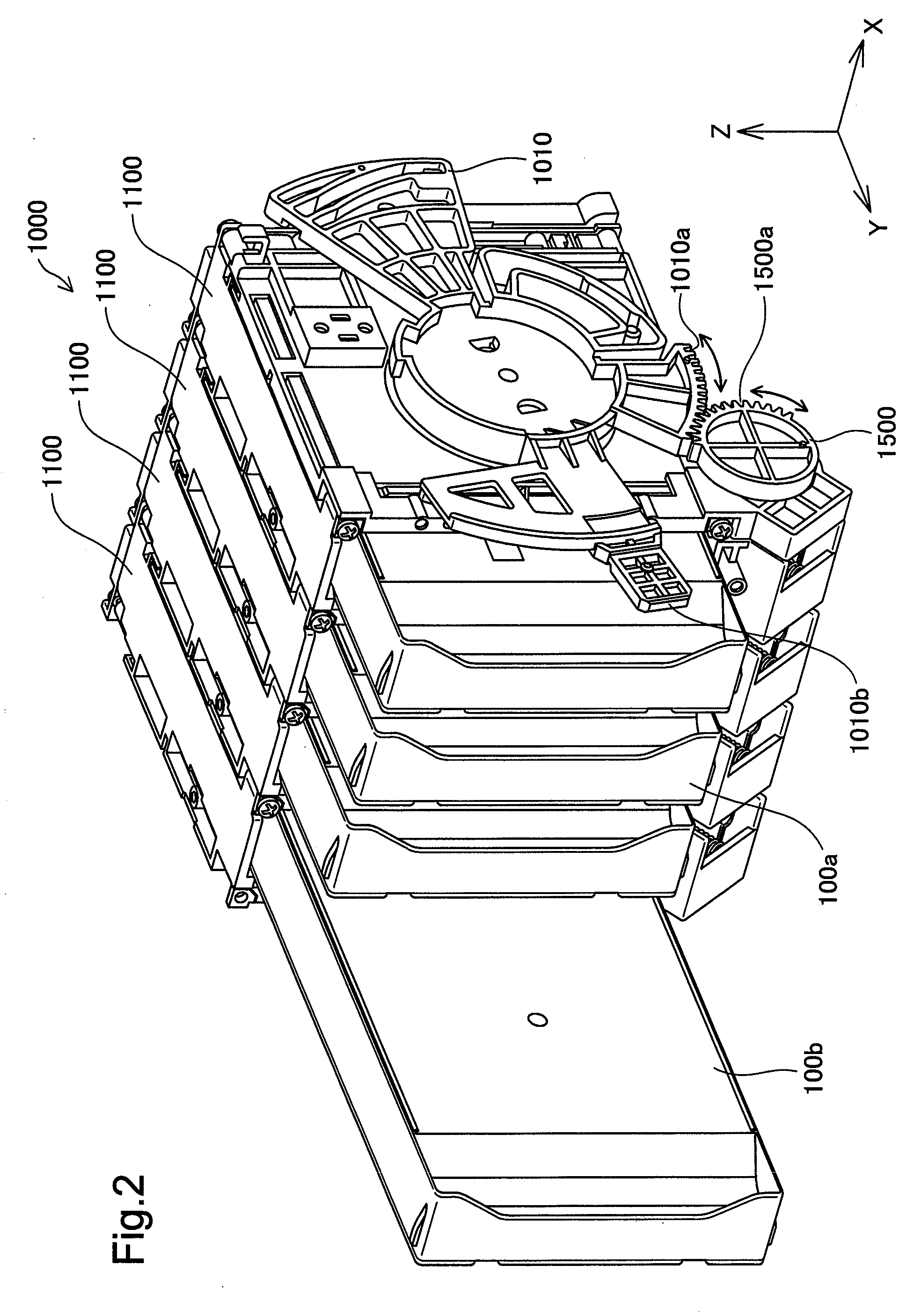
[0057]FIG. 2 is an enlarged view depicting several ink cartridges 100 installed in the holder 1000. The holder 1000 is furnished with holder bodies 1100 equal in number to the installable ink cartridges 100; a lock...


PUM


Abstract

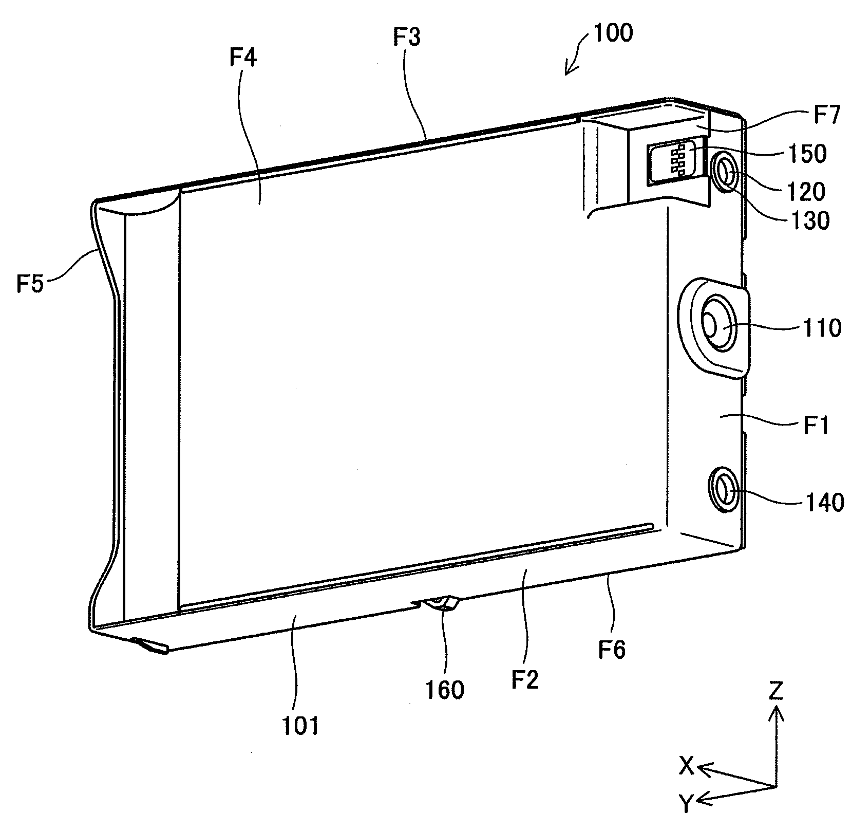
A liquid jetting system includes a liquid container including a front wall, and a side wall having a bias-force receiving part, and a liquid jetting apparatus including a holder that receives installation of the liquid container through insertion of the liquid container in a prescribed insertion direction with the front wall facing forward. The holder further includes a liquid feed needle that receives feed of liquid from the liquid container when the liquid container has been installed, a holder-side electrode situated to a upper side from the liquid feed needle and adapted to electrically connect with the liquid container when the liquid container has been installed, and bias force part situated to a lower side from the liquid feed needle and adapted to exert a bias force on the bias-force receiving part of the liquid container in a prescribed biasing direction when the liquid container has been installed. The liquid container further includes a feed part having a liquid feed port that opens onto the front wall and that receives insertion of the liquid feed needle when the liquid container has been installed in the holder, and a container-side electrode that is to be secured at such a location as to electrically connect with the holder-side electrode when the liquid container has been installed in the holder. The biasing direction is established such that an extended line extending in the biasing direction from the bias-force receiving part is offset from the container-side electrode towards the side wall side.

Description

CROSS REFERENCE TO RELATED APPLICATIONS[0001]This application relates to and claims priority from Japanese Patent Application No. 2008-077733, filed on Mar. 25, 2008 and Japanese Patent Application No. 2008-077741, filed on Mar. 25, 2008, the entire disclosure of which is incorporated by reference.BACKGROUND[0002]1. Technical Field[0003]The present invention relates to a liquid container, to a liquid jetting system, to a holder, and to a liquid jetting apparatus equipped with a holder; and relates in particular to a liquid container that is installable in a holder of a liquid jetting apparatus by being inserted in a prescribed insertion direction, to a liquid jetting system incorporating the liquid container, to a holder adapted to receive installation of the liquid container by insertion in a prescribed insertion direction, and to a liquid jetting apparatus equipped with the holder.[0004]2. Related Art[0005]In the field of ink-jet printers, designs whereby the ink-jet printer is su...

Claims


Application Information

Patent Timeline
IPC IPC(8): B41J2/175
CPCB41J2/1752B41J2/17553B41J2/1753
Inventor KOIZUMI, YOSHIHIROIWAMURO, TAKESHIMATSUMOTO, HITOSHIKIMURA, HITOTOSHI
Owner SEIKO EPSON CORP
Learn More