
Liquid droplet jetting apparatus

a technology of liquid droplet and jetting surface, which is applied in the direction of inking apparatus, power drive mechanism, printing, etc., can solve the problems of curled paper coming into contact with the liquid droplet jetting surface of the recording head, and is not possible, so as to suppress the curling of the object and reduce the curling of this portion

Active Publication Date: 2009-10-01
BROTHER KOGYO KK
View PDF13 Cites 14 Cited by
  • Summary
  • Abstract
  • Description
  • Claims
  • Application Information

AI Technical Summary

Benefits of technology

[0007]The present invention is made in view of the abovementioned circumstances, and an object of the present invention is to provide a liquid droplet jetting apparatus which is capable of suppressing a curling of a recording medium in one direction intersecting the transport direction.
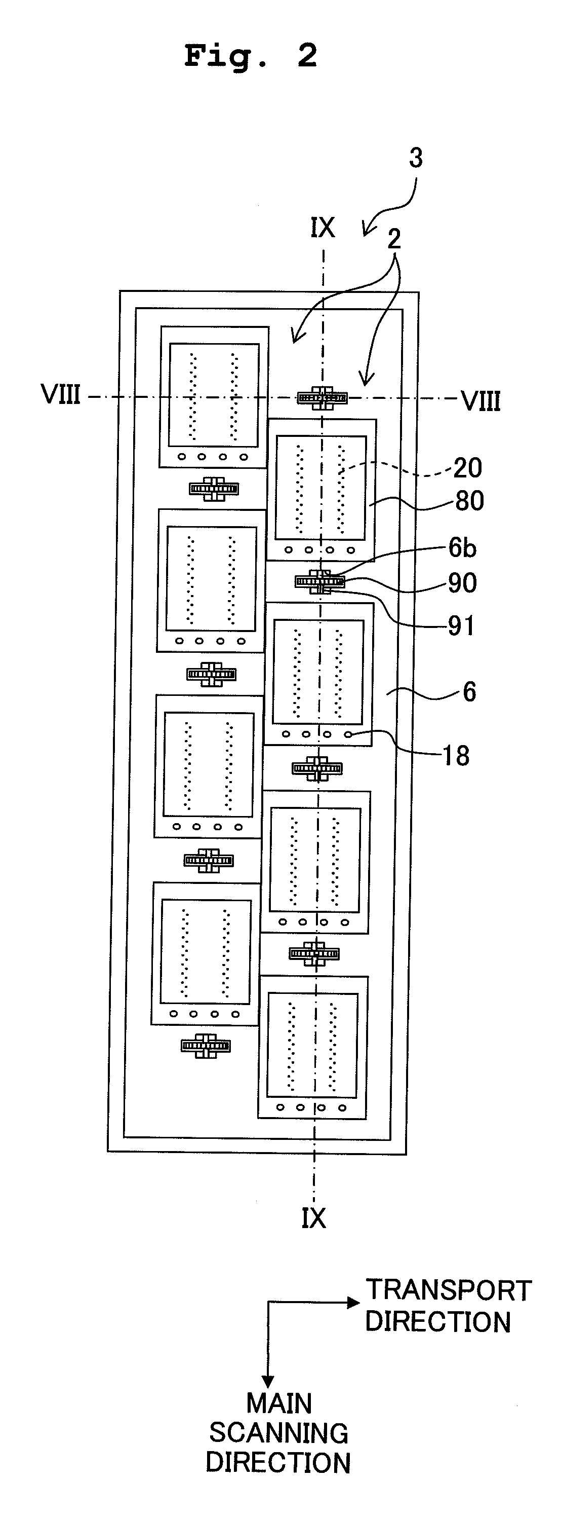
[0014]According to the first aspect of the present invention, the head units adjacent in the transport direction are arranged to be shifted in the one direction (direction in which the nozzle row is aligned) intersecting the transport direction, and further, the pressing mechanism is arranged in that empty space. Accordingly, the head units and the pressing mechanisms are arranged in line in one direction. In other words, a position of the pressing mechanism with respect to the two adjacent head units in the transport direction differs in the one direction, and it is possible to suppress a curling of an object such as a recording paper in this direction.
[0018]According to the second aspect of the present invention, since the two pressing mechanisms are arranged sandwiching the jetting area of the liquid droplet jetting surface, the pressing mechanisms are capable of pressing a portion of the object on which the liquid droplets are going to be jetted, and it is possible to reduce the curling of this portion.
[0019]In the two head units adjacent in the transport direction, the positions of the pressing mechanisms are misaligned in the direction in which the nozzles are arranged in a row. Accordingly, it is possible to suppress the curling of the object (recording medium) in this direction.

Problems solved by technology

Therefore, it is not possible to press an area of the paper facing the recording head in the width direction, and since it is not possible to suppress the curling of paper in the width direction, there is a fear that the curled paper comes in contact with a liquid droplet jetting surface of the recording head.

Method used


Image

  • Liquid droplet jetting apparatus
  • Liquid droplet jetting apparatus
  • Liquid droplet jetting apparatus

Examples


Embodiment Construction

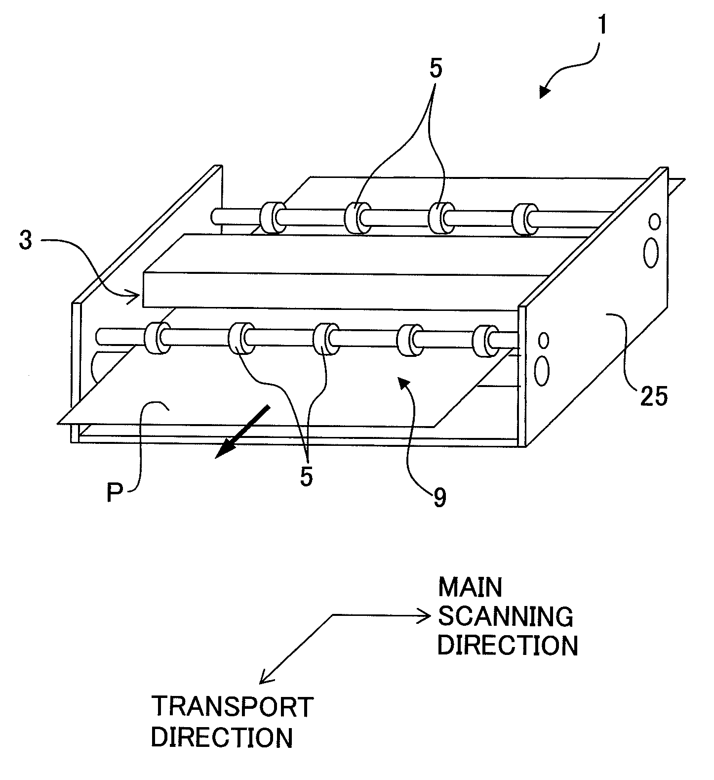
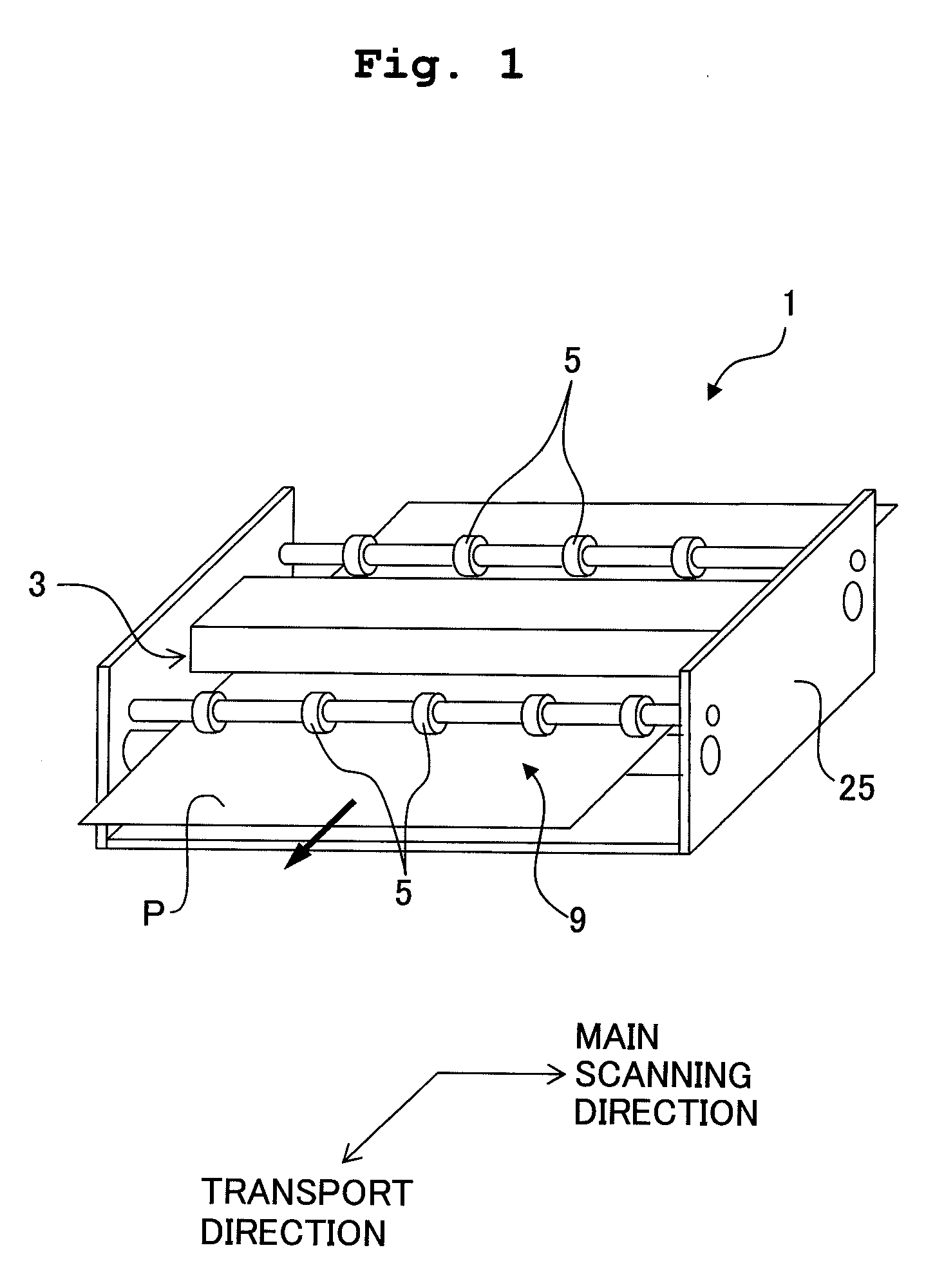
[0035]Next, an ink-jet printer according to an embodiment of the present invention will be described below. The ink-jet printer in the embodiment includes a line ink-jet head in which a plurality of head units and a plurality of spurs are arranged alternately in line along a predetermined direction. FIG. 1 is a schematic structural view of the ink-jet printer according to the embodiment of the present invention.

[0036]As shown in FIG. 1, an ink-jet printer 1 (liquid droplet jetting apparatus) includes a line ink-jet head 3 which is extended in a left-right direction in FIG. 1 (a first direction, a direction in which the line ink-jet head is extended, a direction in which a row of nozzles is extended, a main scanning direction), and which jets an ink onto a recording paper P (recording medium), and a transporting mechanism 9 which transports the recording paper P frontward (transport direction orthogonal to the main scanning direction: secondary scanning direction). The ink is jetted ...


PUM


Abstract

An ink-jet printer has a line ink-jet head which includes a plurality of heat units arranged in two rows in a zigzag form along a main scanning direction, and a spur which is arranged to be in line in the main scanning direction, with a first head unit belonging to one row, and to overlap a second head unit adjacent to the first head unit, which belongs to the other row, in a direction intersecting the main scanning direction. The spur presses a recording paper from a side of the head unit. Accordingly, it is possible to suppress curling of the recording paper in a direction intersecting a transport direction.

Description

CROSS REFERENCE TO RELATED APPLICATION[0001]The present application claims priority from Japanese Patent Application No. 2008-091651, filed on Mar. 31, 2008 the disclosures of which are incorporated herein by reference in its entirety.BACKGROUND OF THE INVENTION[0002]1. Field of the Invention[0003]The present invention relates to a liquid droplet jetting apparatus which jets liquid droplets from nozzles formed in a head unit or head units.[0004]2. Description of the Related Art[0005]A line type ink-jet recording apparatus which records an image and characters by jetting droplets of an ink from nozzles of a recording head, on to a recording medium such as a paper which is transported by a transporting unit has hitherto been available. In such ink-jet recording apparatus, when the ink droplets jetted from the nozzles are landed on and permeated into the paper, an area of the paper in which the ink has permeated contracts in a planar direction, and an end portion near the area of the p...

Claims


Application Information

Patent Timeline
Patent Type & Authority Applications(United States)
IPC IPC(8): B41J2/01
CPCB41J2/14233B41J2/15B41J2/155B41J2202/20B41J2002/14266B41J2002/14362B41J2002/14459B41J11/0005
Inventor SUGAHARA, HIROTO
Owner BROTHER KOGYO KK
Learn More