Methods and systems to mitigate inter-cell interference

a technology of inter-cell interference and mitigation methods, applied in the field of wireless communication, can solve the problems of reducing network capacity, performance degradation, and difficulty in suppressing inter-cell interference to improve coverage, and achieve the effect of reducing inter-cell interferen

Active Publication Date: 2009-10-01
MICROSOFT TECH LICENSING LLC
View PDF13 Cites 81 Cited by
  • Summary
  • Abstract
  • Description
  • Claims
  • Application Information

AI Technical Summary

Benefits of technology

[0009]According to a first aspect of the invention there is provided a method for execution in an OFDM communications environment having a plurality of cells, comprising: for a transmitter corresponding to a first cell; partitioning a time-frequency transmission resource comprising a plurality of sub-carriers over a plurality of OFDM symbol intervals into a first zone and a second zone; in the first zone, transmitting on at least one set of sub-carriers which is used by all of the plurality of cells; in the second zone, transmitting on at least one set of sub-carriers which is used by less than all of the plurality of cells so as to mitigate inter-cell interference.

Problems solved by technology

Suppressing inter-cell interference to improve coverage and increase cell edge bit rates, however, is a challenge.
One drawback to such an approach is that it dramatically reduces network capacity, as compared to a frequency re-use-1 scheme where each cell uses all of the available bandwidth.
While such an approach achieves a spreading gain, performance degradation occurs as a result of orthogonality loss.
In addition, when using such a scheme decoding and decoding hardware complexity increases.
Such an approach, however, introduces more complexity to the network.
Similarly, inter-cell interference cancellation techniques introduce more complexity in the receiver and are, therefore, not practical to be implemented everywhere.

Method used


Image

  • Methods and systems to mitigate inter-cell interference
  • Methods and systems to mitigate inter-cell interference
  • Methods and systems to mitigate inter-cell interference

Examples


Embodiment Construction

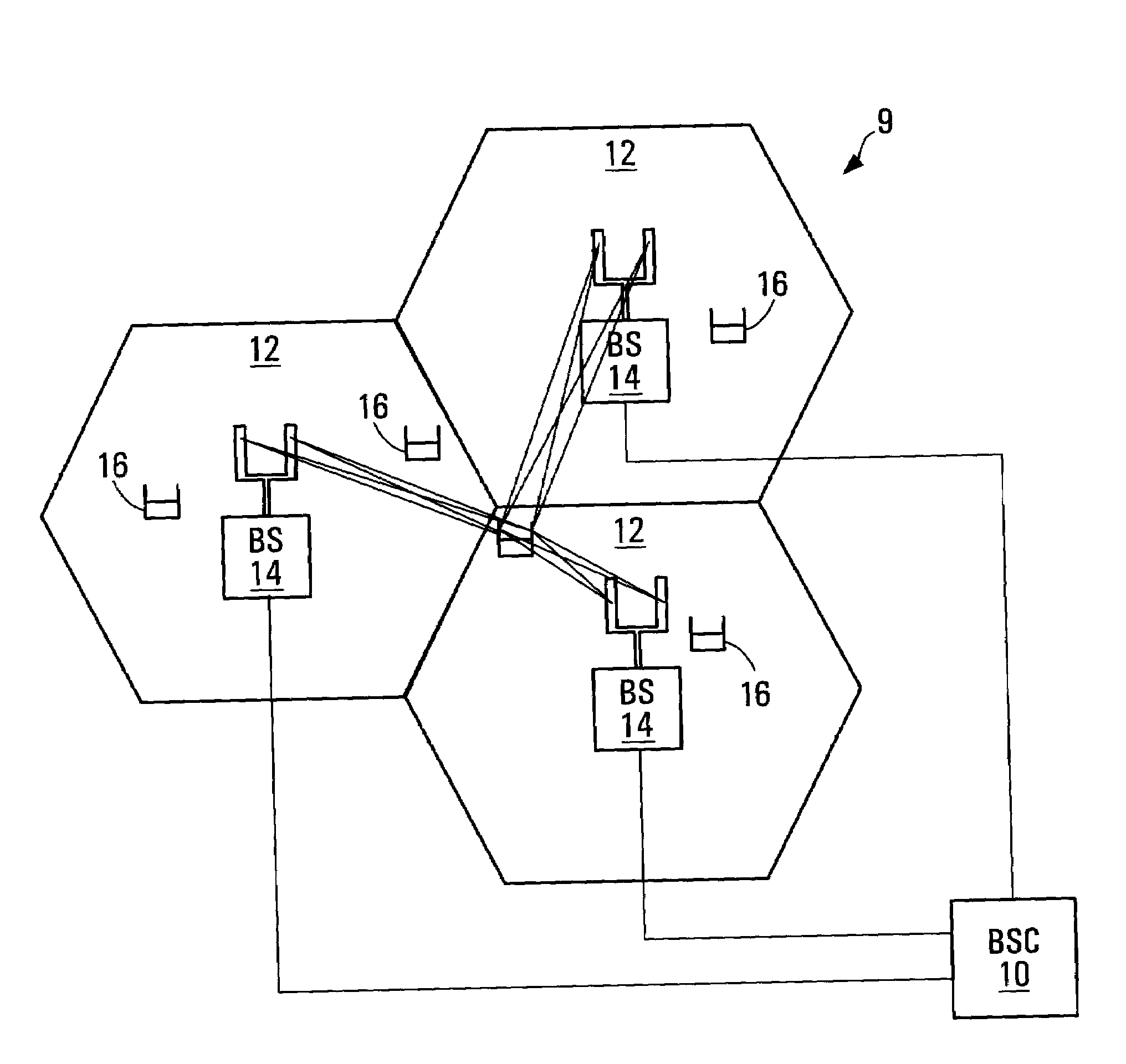
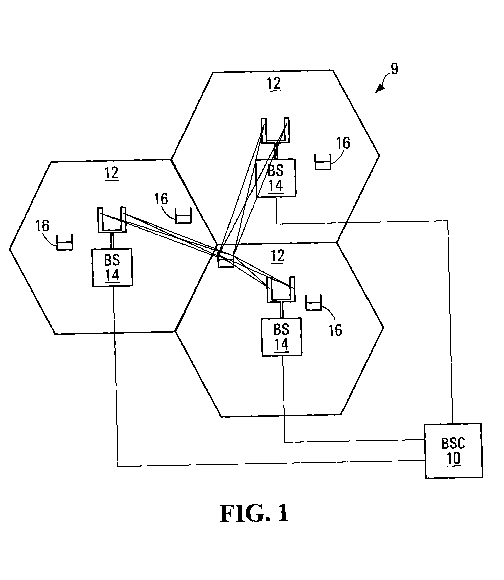
[0060]FIG. 1 illustrates an example of a communications environment 9 having three cells 12. FIG. 1 shows a base station controller (BSC) 10 that controls wireless communications within the three cells 12, in which each cell is served by a respective base station (BS) 14. In general, each respective base station 14 facilitates communication using OFDM with mobile and / or wireless terminals 16, which are within the cell 12 associated with the respective base station 14. The movement of the mobile terminals 16 in relation to the base stations 14 results in significant fluctuation in channel conditions. As illustrated, the base stations 14 and wireless terminals 16 may include multiple antennas to provide spatial diversity for communications.

[0061]In some implementations a wireless terminal 16 is a wireless device such as a cellular telephone, computer with a wireless modem, or PDA. In some implementations the wireless terminal has a fixed location. In other implementations the wireless...


PUM


Abstract

The present invention provides methods and devices for mitigating inter-cell interference in communication environments having a plurality of cells. In some embodiments, a time-frequency transmission resource that includes multiple sub-carriers over multiple OFDM symbol intervals is partitioned into a first zone and a second zone. In the first zone, transmissions are transmitted on at least one frequency sub-band which is common to all of the plurality of cells. In the second zone, transmissions are transmitted on at least one frequency sub-band which is used by less than all of the plurality of cells, so as to mitigate inter-cell interference. In some embodiments, in the first zone transmissions are transmitted using a transmission power which is common to all of the plurality of cells and in the second zone transmissions are transmitted using a transmission power which is used by less than all of the plurality of cells so as to mitigate inter-cell interference.

Description

RELATED APPLICATIONS [0001]This application claims the benefit of U.S. Provisional Patent Application No. 60 / 710,584, filed on Aug. 23, 2005, which is hereby incorporated by reference in its entirety.FIELD OF THE INVENTION [0002]The invention generally relates to the field of wireless communications. More specifically, the invention relates to mitigating inter-cell interference in communication environments using an orthogonal frequency division multiplexing (OFDM) based air interface or a transformed OFDM based air interface.BACKGROUND OF THE INVENTION [0003]A frequency re-use-1 scheme is commonly employed in OFDM based cellular networks. The frequency re-use-1 scheme involves each cell in a communication network using the same available bandwidth. Suppressing inter-cell interference to improve coverage and increase cell edge bit rates, however, is a challenge. A number of techniques have been considered to mitigate inter-cell interference.[0004]One way is to use a fractional frequ...

Claims


Application Information

Patent Timeline
Patent Type & Authority Applications(United States)
IPC IPC(8): H04W72/04H04W16/02H04W16/12
CPCH04L5/0007H04L5/0032H04L5/0046H04W16/12H04L5/0062H04W16/02H04L5/0048H04L5/0023H04L5/0057H04L5/0073
Inventor MA, JIANGLEIJIA, MINGTONG, WENZHU, PEIYINGLE STRAT, EVELYNEBOUMENDIL, SARAH
Owner MICROSOFT TECH LICENSING LLC
Why Eureka
Try Eureka