Characterization of flaws in composites identified by thermography

a composite and thermography technology, applied in the field of thermography, can solve the problems of not identifying what types of flaws were found and not disclosing

Active Publication Date: 2009-10-01
GENERAL ELECTRIC CO
View PDF47 Cites 33 Cited by
  • Summary
  • Abstract
  • Description
  • Claims
  • Application Information

AI Technical Summary

Benefits of technology

[0014]One embodiment of the method further includes displaying areas of the object corresponding to the pixels characterized by the different types of flaws and no flaws. Another more

Problems solved by technology

Thermography has been used to locate the flaws that alter the flow of heat but did not identify what types of flaws were found

Method used


Image

  • Characterization of flaws in composites identified by thermography
  • Characterization of flaws in composites identified by thermography
  • Characterization of flaws in composites identified by thermography

Examples


Embodiment Construction

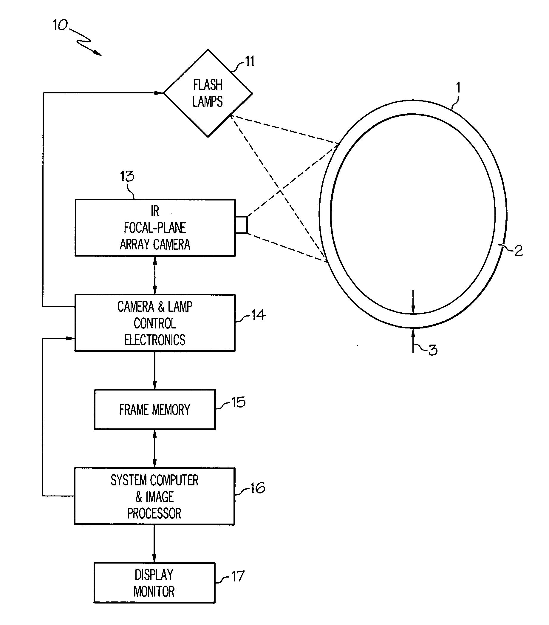
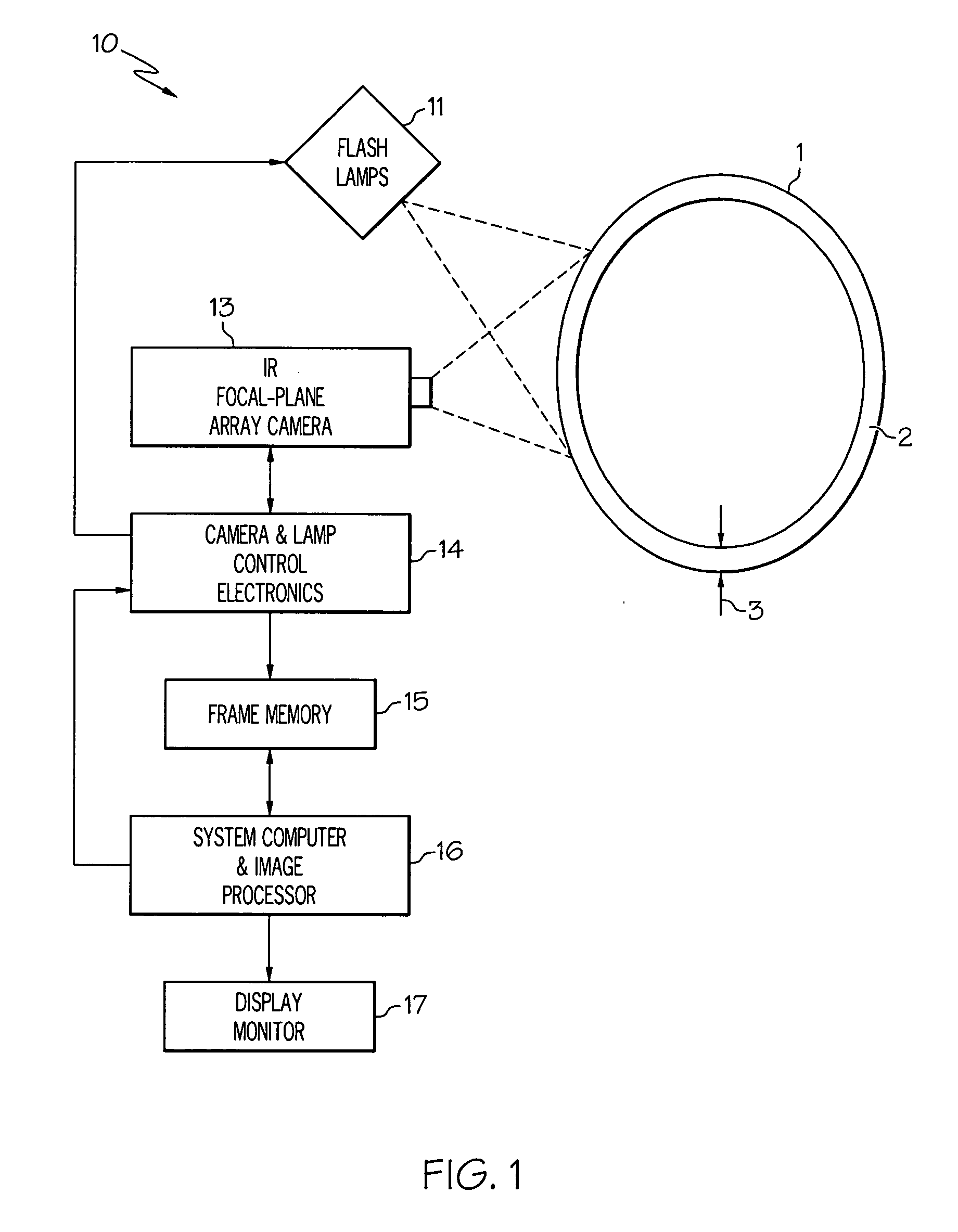
[0025]Illustrated in FIG. 1 is an IR transient thermography system 10 for identifying and characterizing flaws, e.g. delaminations and porosity, in a composite object 1, e.g. a composite gas turbine engine combustor liner having a composite wall 2 of thickness 3. A flash-lamp heat-pulse source 11 is used to rapidly heat the surface of the object being analyzed. One suitable arrangement for flash-lamp heat-pulse source 11 would be, for example, a set of four or eight high-speed, high output power photographic flash-lamps, each capable of about 4.8 Kilo-joules output and having individual power supplies (such as, for example, flash-lamps manufactured by Speedotron, Corp. in Chicago, Ill.).

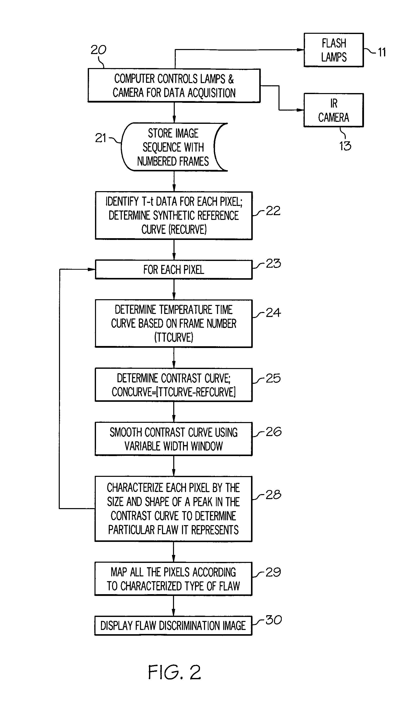
[0026]An exemplary infrared transient thermography method for determining and characterizing flaws in articles made of composite materials is outlined in blocks of a flow chart illustrated in FIG. 2 and using the system illustrated in FIG. 1. Surface temperature measurements of heat-pulse illuminated...


PUM


Abstract

A method for identifying types of flaws in a composite object includes: a) rapidly heating the surface of the object; b) recording pixel intensities in a sequence of IR images; c) determining temperature-versus-time data for each of the pixels from the IR images; and d) determining what type of flaw if any corresponds to each of the pixels using the temperature-versus-time data determined in step (c). A contrast curve derived from the temperature-versus-time data may be used in determining what type of flaws if any corresponds to each of the pixels. The contrast curve may be determined by subtracting a synthetic reference curve from a temperature time curve from the temperature-versus-time data. The types of flaws may be determined from size and/or shapes of peaks in the contrast curves. Some flaws are delaminations, layers of porosity, and uniformly distributed porosity.

Description

BACKGROUND OF THE INVENTION[0001]1. Field of the Invention[0002]This invention relates generally to thermography and, more particularly, to using thermography to identify flaws in articles made of composite materials.[0003]2. Description of Related Art[0004]Thermography has been used to locate flaws in articles including articles made of composite materials. Composite materials include both polymers and ceramics. Thermography has been used to show flaws appearing in composites via their characteristic time-temperature contrast signatures obtained with infrared thermography. Thermography has been used to locate the flaws that alter the flow of heat but did not identify what types of flaws were found. Flaws in composites typically include porosity and delaminations.[0005]Thermography is a non-destructive evaluation (NDE) technique in which heat is applied to an object and a resulting temperature distribution on a surface of the object is measured over time with an infrared camera. Inf...

Claims


Application Information

Patent Timeline
IPC IPC(8): G01N25/72
CPCG01N25/72
Inventor RINGERMACHER, HARRY ISRAELHOWARD, DONALD ROBERTKNIGHT, BRYON EDWARDPATTERSON, WILLIAM GEORGEBANTEL, THOMAS EDWARD
Owner GENERAL ELECTRIC CO
Why Eureka
Try Eureka