Scroll compressor

a compressor and scroll technology, applied in the direction of machines/engines, rotary/oscillating piston pump components, liquid fuel engines, etc., to achieve the effect of improving performance and reliability of scroll compressors, reducing start load, and stabilizing the movement of orbit scrolls

Inactive Publication Date: 2009-10-01
SANYO ELECTRIC CO LTD
View PDF3 Cites 17 Cited by
  • Summary
  • Abstract
  • Description
  • Claims
  • Application Information

AI Technical Summary

Benefits of technology

[0014]Furthermore, since the spring member urges the eccentric shaft to press the eccentric shaft onto the slide face of the slide bush, the eccentric shaft can constantly be pressed onto the slide face of the slide bush, to come in close contact with the slide face. In consequence, it is possible to securely eliminate a disadvantage that the slide face of the slide bush comes away from the eccentric shaft to cause backlash.
[0015]In general, while suppressing the start load, the moving of the orbit scroll can be stabilized, and the performance and the reliability of the scroll compressor can be improved.
[0016]In particular, according to the second aspect of the present invention, the first aspect of the present invention further comprises the spring receiving portion formed in the inner surface of the slide bush to receive the spring member, and the spring receiving portion on the side of the orbit scroll is provided with a closing portion which regulates the movement of the spring member. Therefore, the closing portion can avoid in advance a disadvantage that the spring member jumps out toward the orbit scroll.

Problems solved by technology

However, in the scroll compressor in which the spring member presses the eccentric shaft in the eccentric direction as described above to obtain a variable eccentric amount of the eccentric shaft, a problem occurs that during an operation, the slide face of the slide bush comes away from the eccentric shaft to cause backlash.

Method used


Image

  • Scroll compressor
  • Scroll compressor
  • Scroll compressor

Examples


Embodiment Construction

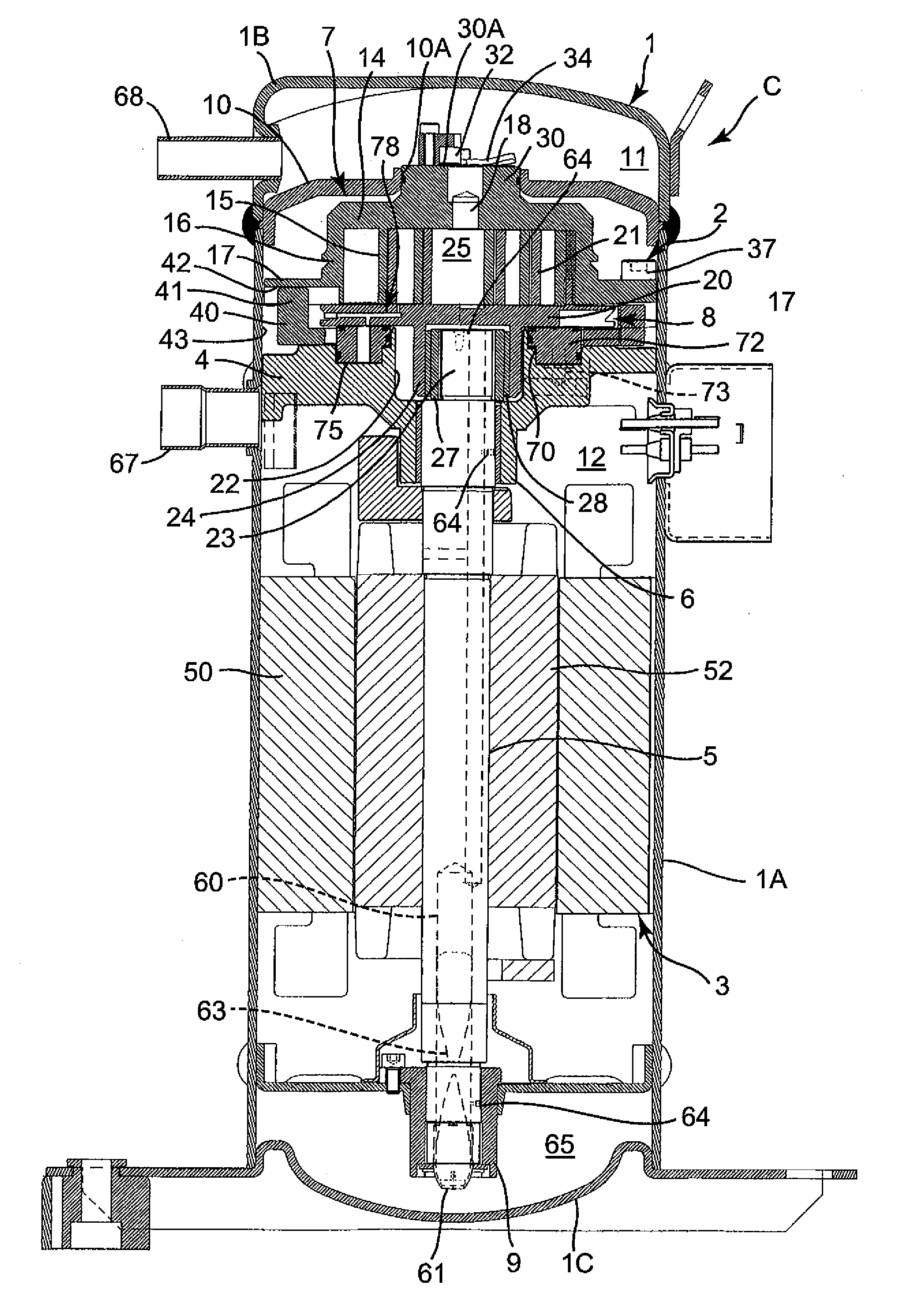
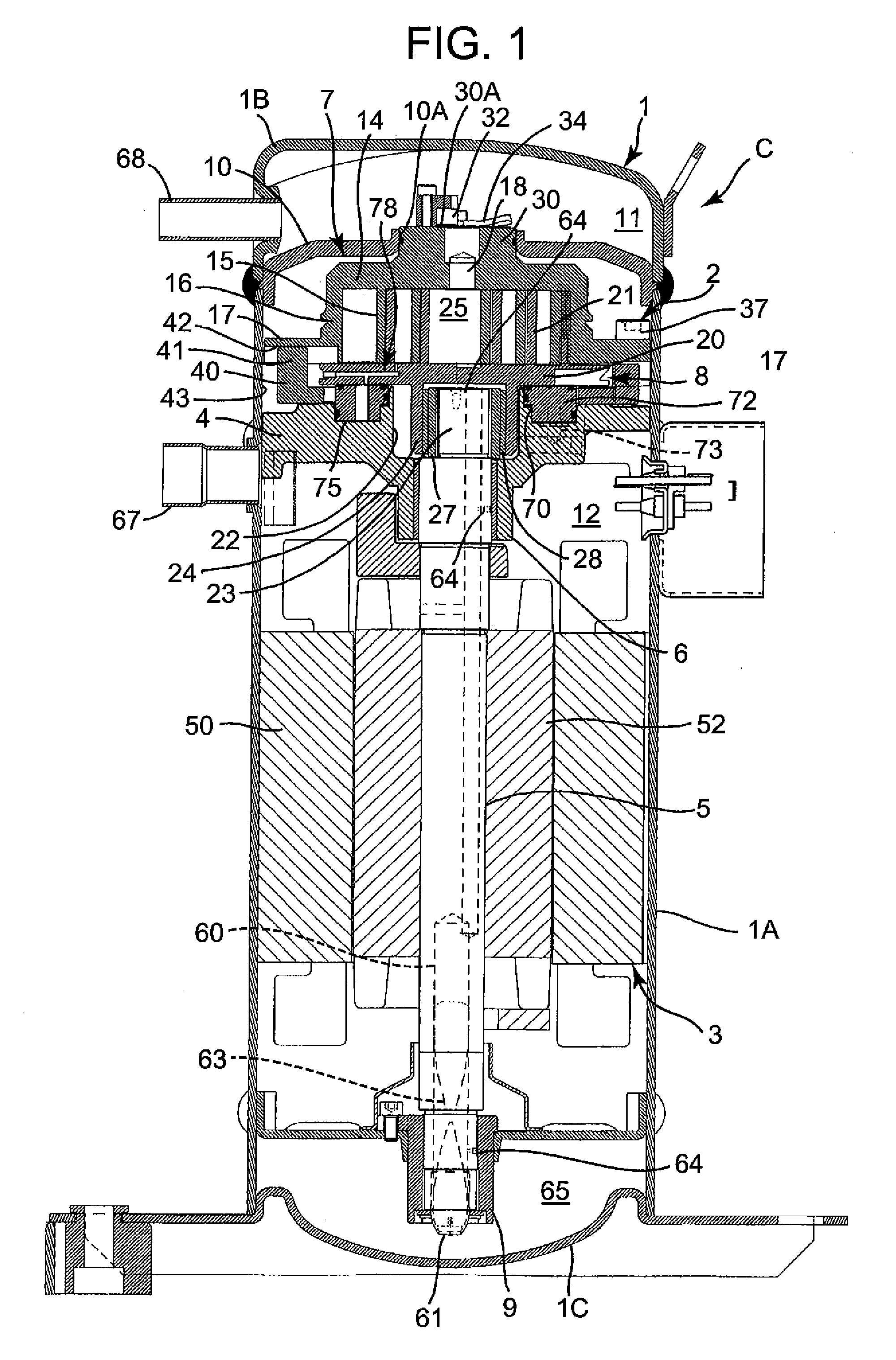
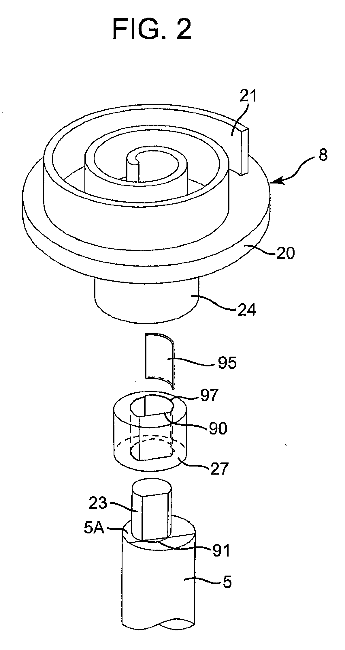
[0024]The present invention has been developed to eliminate a problem that the moving of an orbit scroll becomes unstable, for example, a problem that the slide face of a slide bush comes away from an eccentric shaft during an operation, in a scroll compressor in which a spring member is interposed between the slide bush and the eccentric shaft, and presses the eccentric shaft in an eccentric direction, to obtain the variable eccentric amount of the eccentric shaft. Thus, an object to stabilize the moving of the orbit scroll while suppressing the start load of the scroll compressor is realized by interposing, between the slide bush and the eccentric shaft, the spring member which constantly urges the eccentric shaft to decrease the eccentric amount of the eccentric shaft and which urges the eccentric shaft to press the eccentric shaft onto the slide face of the slide bush. Hereinafter, an embodiment of the present invention will be described with reference to the drawings.

[0025]FIG....


PUM


Abstract

There is disclosed a scroll compressor having an object of stabilizing the moving of an orbit scroll while suppressing the start load of the scroll compressor. In the scroll compressor, a slide bush having a slide face forming a predetermined angle with respect to the direction of gas load of a gas in a compression chamber is interposed on an eccentric shaft of a shaft for driving the orbit scroll, so that when the load of the gas in the compression chamber is applied, the eccentric amount of the eccentric shaft increases. The scroll compressor includes a spring member interposed between the slide bush and the eccentric shaft and configured to constantly urge the eccentric shaft to decrease the eccentric amount of the eccentric shaft, and this spring member urges the eccentric shaft to press the eccentric shaft onto the slide face of the slide bush.

Description

BACKGROUND OF THE INVENTION[0001]The present invention relates to a scroll compressor in which laps are formed on the mutually facing faces of a fixed scroll and a mirror plate of an orbit scroll which revolves in the orbit with respect to the fixed scroll, and the laps are engaged with each other to form a plurality of compression chambers.[0002]Heretofore, this type of scroll compressor has a fixed scroll and an orbit scroll which revolves in the orbit with respect to this fixed scroll, spiral laps are formed on the mutually facing faces of the fixed scroll and a mirror plate of the orbit scroll, and the laps are engaged with each other to form a plurality of compression chambers.[0003]A slide bush is interposed on an eccentric shaft of a motor which drives the orbit scroll. This slide bush has a slide face forming a predetermined angle with respect to the direction of gas load of a gas in each compression chamber. When the load of the gas in the compression chamber is applied, th...

Claims


Application Information

Patent Timeline
Patent Type & Authority Applications(United States)
IPC IPC(8): F01C1/02
CPCF04C18/0215F04C29/0071F04C28/22
Inventor SUGIMOTO, KAZUYOSHISATO, KAZUYA
Owner SANYO ELECTRIC CO LTD
Why Eureka
Try Eureka