
Method of aligning nanotubes

a nanotube and nanotube technology, applied in the field of nanotube alignment, can solve the problems of high entanglement and unpredictable electrical properties, limit the choice of substrate materials, and the defects of nanotubes that are usually grown

Active Publication Date: 2009-10-01
NANYANG TECH UNIV
View PDF10 Cites 47 Cited by
  • Summary
  • Abstract
  • Description
  • Claims
  • Application Information

AI Technical Summary

Benefits of technology

The present invention relates to a method of aligning nanotubes by allowing a suspension of nanotubes to flow in one or more channels to align the nanotubes in a direction parallel to the longitudinal axis of the channels. This method can be used to create a collective alignment of nanotubes that form a conductive path, even if some nanotubes are not perfectly aligned in the same direction as others. The resulting arrangement of nanotubes has improved conductivity and can be used in various applications such as electronics and sensors.

Problems solved by technology

The formed nanotubes were randomly distributed, highly entangled and had unpredictable electrical properties.
However, their high processing temperature (typically >800° C.) significantly limits the choice of substrate materials.
Furthermore, the as-grown nanotubes usually have many defects and, as such, have varying conductivity.
The method of Lieber et al is, however, not suitable for nanotubes because it relies on the nanowires' inherent rigidity, which nanotubes do not have.
In particular, Heath et al noted that Lieber et al used rigid nanowires with controlled length and diameter, and that these were not conditions that could be replicated for nanotubes due to the flexibility and lack of dimensional control of individual nanotubes.

Method used


Image

  • Method of aligning nanotubes
  • Method of aligning nanotubes
  • Method of aligning nanotubes

Examples


Embodiment Construction

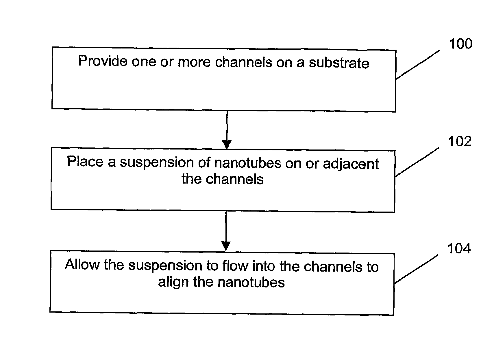
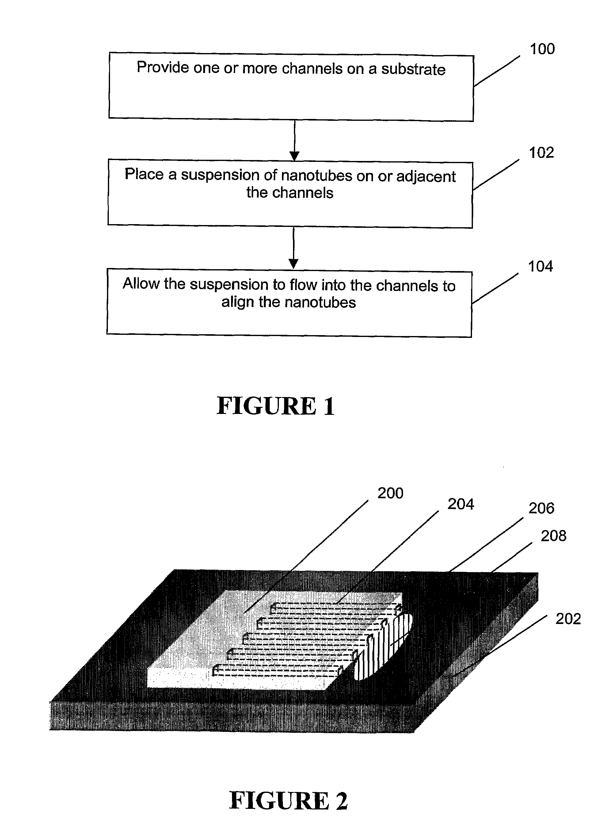
[0021]Referring to FIG. 1, a flow chart of one form of the method is shown. The method includes providing a plurality of channels on a substrate (100), positioning a suspension of nanotubes for flowing into the channels (102), and allowing the suspension to flow into the channels to align the nanotubes (104).

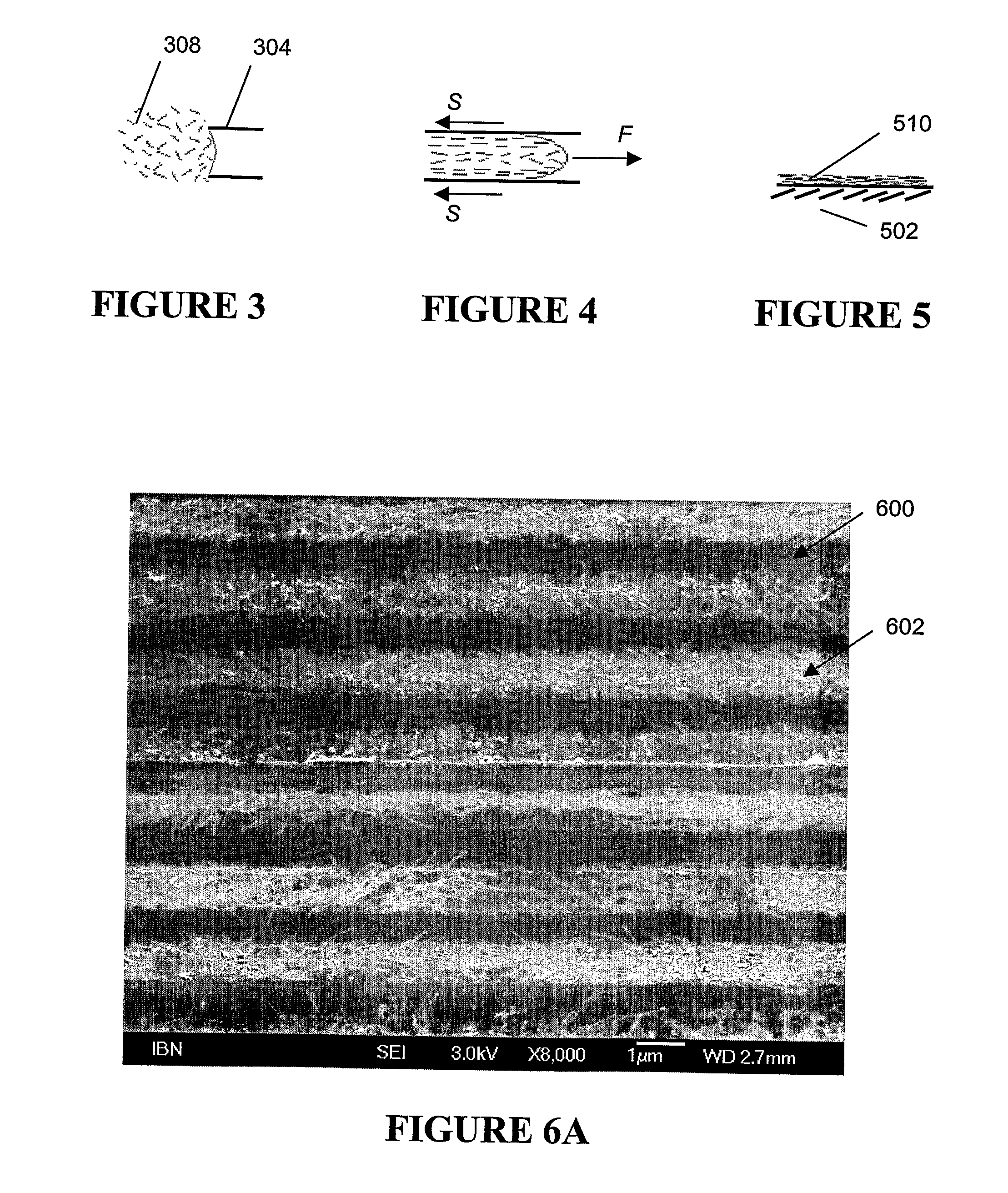
[0022]In a first example embodiment, a plurality of channels is provided by assembling a mold and a substrate. The mold includes lengthwise-open relief structures or channels that form lengthwise-closed channels when placed on a substrate. In this embodiment, a suspension of nanotubes is positioned at or adjacent an open surface of the lengthwise-closed channels and is drawn into the lengthwise-closed channels by virtue of capillary attraction. The capillary attraction generates a shear force within the suspension, which aligns the nanotubes substantially parallel to the longitudinal axis of the channels.

[0023]A schematic of the first example embodiment is shown in FIG. 2. The f...


PUM


Abstract

A method of aligning nanotubes is described, where a plurality of channels is provided on a substrate (100), a suspension of nanotubes is placed on or adjacent an open surface of the channels (102) and the suspension is allowed to flow into the channels to align the nanotubes substantially parallel to the longitudinal axis of the channels (104).

Description

FIELD OF THE INVENTION[0001]The present invention relates to a method of aligning nanotubes. In particular, but not exclusively, the present invention relates to a method of aligning nanotubes in one or more microchannels using fluidic alignment.BACKGROUND TO THE INVENTION[0002]Nanotubes, in particular carbon nanotubes (CNTs), are essentially one-dimensional metallic or semiconducting materials. The electrical properties of nanotubes are dependent on, amongst others, their dimensions and orientation. When properly formed and oriented, nanotubes provide great electrical current handling capability, high thermal conductivity and high mechanical strength. These properties make nanotubes an ideal material for molecular or nano-scale electronic devices. Examples of electronic devices that have been implemented using CNTs include CNT transistors and CNT sensors.[0003]In the past, nanotubes in the devices were formed by spin-coating or other like techniques. The formed nanotubes were rando...

Claims


Application Information

Patent Timeline
Patent Type & Authority Applications(United States)
IPC IPC(8): H05H1/24B05D3/00
CPCB82Y10/00H01L51/0048H01L51/0012H01L51/0003H10K71/191H10K71/12H10K85/221
Inventor CHAN, BEE ENG MARYZHANG, QINGYAN, YEHAILI, SAICHEN, LONGQING
Owner NANYANG TECH UNIV
Learn More