Swing analyzer

Inactive Publication Date: 2009-10-01
MIZUNO CORPORATION
View PDF32 Cites 95 Cited by
  • Summary
  • Abstract
  • Description
  • Claims
  • Application Information

AI Technical Summary

Benefits of technology

[0022]By the swing analyzer in accordance with the present invention, the swing

Problems solved by technology

Therefore, the shaft is in a very complicated motion during a swing.
By the method described in Japanese Patent Laying-Open No. 3-126477, however, the angular velocity of the shaft in complicated motion cannot accurately be calcul

Method used


Image

  • Swing analyzer
  • Swing analyzer
  • Swing analyzer

Examples


embodiment 1

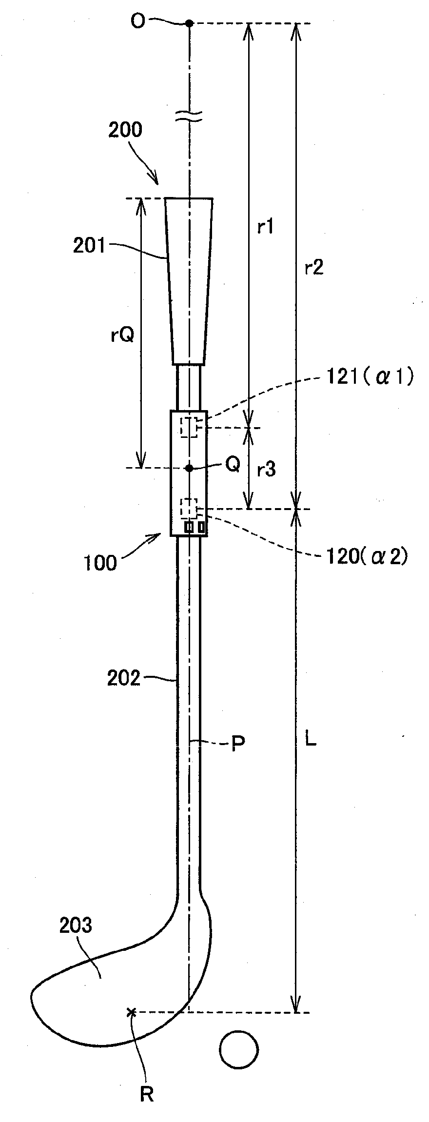
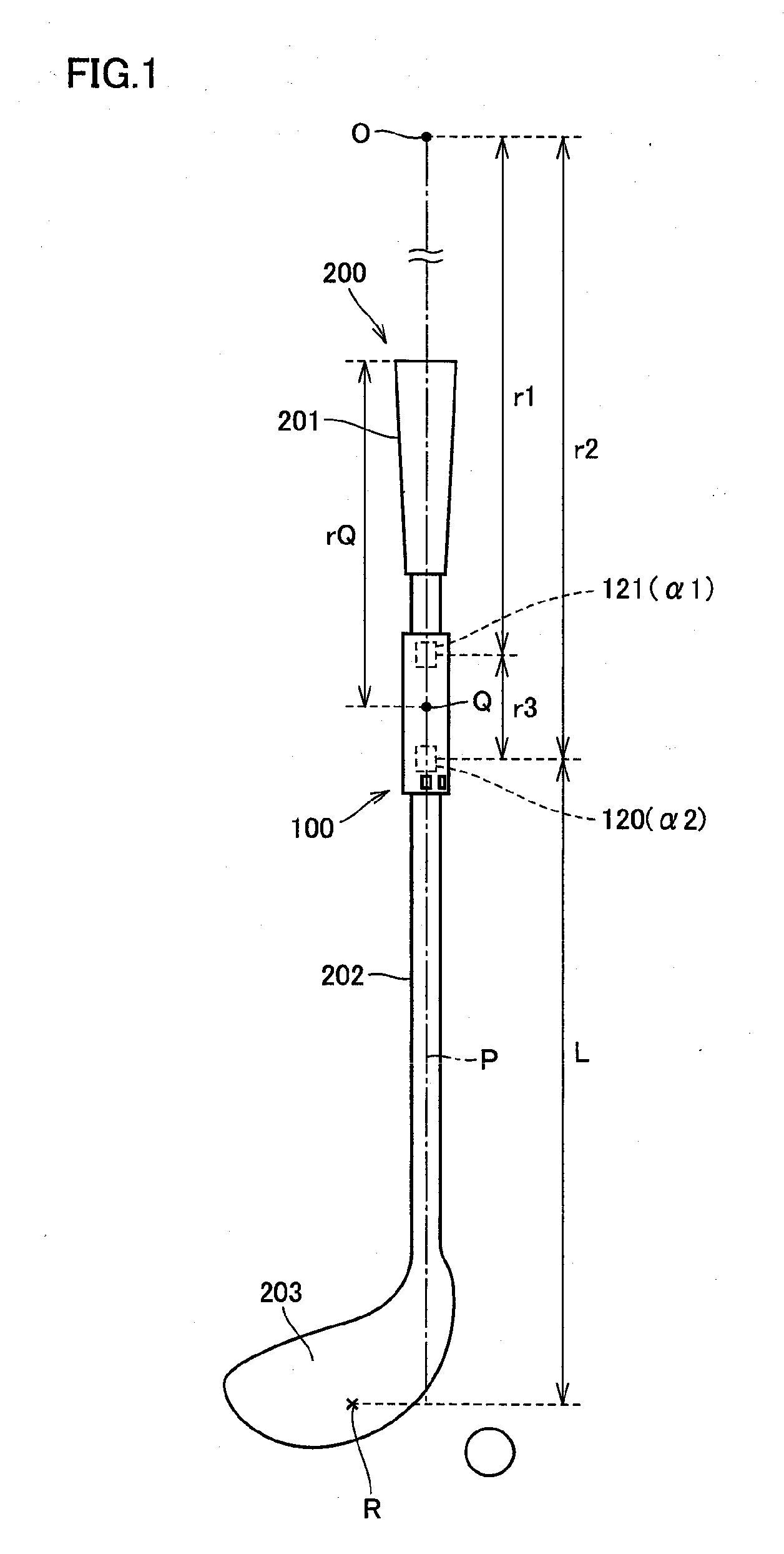
[0118]FIG. 17 shows outer diameter and bending stiffness distribution (El distribution) of golf club shafts used in the method of selecting golf club shaft in accordance with an embodiment of the present invention. In FIG. 17, the abscissa represents a distance from the club-head side end of golf club shaft. In the example shown in FIG. 17, the outer diameter and bending stiffness of a golf club shaft increase from the club head side to the grip side.

[0119]FIG. 17 shows data of three club shafts (butt standard / butt stiff / butt soft) having the same amount of deflection in cantilever model, while having mutually different EI distributions. Details of the “cantilever model” and “butt standard / butt stiff / butt soft” will be described later.

[0120]In the following, the method of measuring bending stiffness distribution of golf club shaft will be described.

[0121]The bending stiffness is calculated by the following equation, based on the inclination of displacement-load, in three-point bendi...


PUM


Abstract

A calculating unit of a swing analyzer calculates, assuming that a golf club is in a uniform circular motion about a virtual center of rotation 0 during a swing, a virtual speed Vh at a central point R of a golf club head, based on a distance between first and second acceleration sensors, a distance between the first acceleration sensor and the central point R of a golf club head and outputs from the first and second acceleration sensors, and calculates the speed of central point R of a golf club head utilizing the virtual speed Vh.

Description

[0001]This nonprovisional application is based on Japanese Patent Application No. 2008-093427 filed with the Japan Patent Office on Mar. 31, 2008, the entire contents of which are hereby incorporated by reference.BACKGROUND OF THE INVENTION[0002]1. Field of the Invention[0003]The present invention relates to a swing analyzer and, more specifically, to a swing analyzer capable of measuring swing speed of a portion as an object of measurement of a swing member.[0004]2. Description of the Background Art[0005]Conventionally, various swing analyzers measuring states of swings of golf or baseball batting have been proposed.[0006]By way of example, Japanese Patent Laying-Open No. 3-126477 discloses a swing analyzing device including a swing implement having a shaft-like part, first and second two acceleration sensors arranged spaced apart by a distance on the shaft-like part with the direction of acceleration detection substantially matching axial line of the shaft-like part, and a transla...

Claims


Application Information

Patent Timeline
IPC IPC(8): A63B69/36A63B53/00A63B102/32
CPCA63B69/3632A63B2220/10A63B2220/833A63B2220/54A63B2220/40
Inventor SATO, FUMINOBUNAGAO, HIROSHIKIMURA, TAKASHI
Owner MIZUNO CORPORATION
Why Eureka
Try Eureka