Vehicle clip centering device and method

a technology of vehicle clip and centering device, which is applied in the direction of screws, roofs, doors, etc., can solve the problems of affecting the alignment of the fastener with the aperture provided in the components that are to be attached to, the loss of retention strength of the fastener or its associated clip(s) and housing, and the component can become loose or rattle, etc., to achieve the effect of reducing vibration, reducing rattling, and reducing nois

Active Publication Date: 2009-10-08
HONDA MOTOR CO LTD
View PDF21 Cites 19 Cited by
  • Summary
  • Abstract
  • Description
  • Claims
  • Application Information

AI Technical Summary

Benefits of technology

[0009]The disclosed subject matter addresses at least some of the drawbacks of conventional fastener systems by providing an assembly that centers a clip within a clip base so that components can be releasably coupled to each other in a manner that also reduces and/or eliminate

Problems solved by technology

A common problem with such conventional fastening devices has been that, during assembly, alignment of the fasteners with the apertures provided in the components that are to be attached to can be difficult.
As a result, misaligned fasteners or clips cause poor coupling of components which may overstress both the fastener/clip and the components to be coupled, resulting in a loss in retention strength for holding the components in place and/or destruction of the fastener or associated clip(s) and housings.
As a result, components can become loose or rattle because of improper fastener geometry or installation.
In such conventional structures, there has been difficulty centering the pin and grommet within the socket structure.
Sometimes, the pin is forced to an e

Method used


Image

  • Vehicle clip centering device and method
  • Vehicle clip centering device and method
  • Vehicle clip centering device and method

Examples


Embodiment Construction

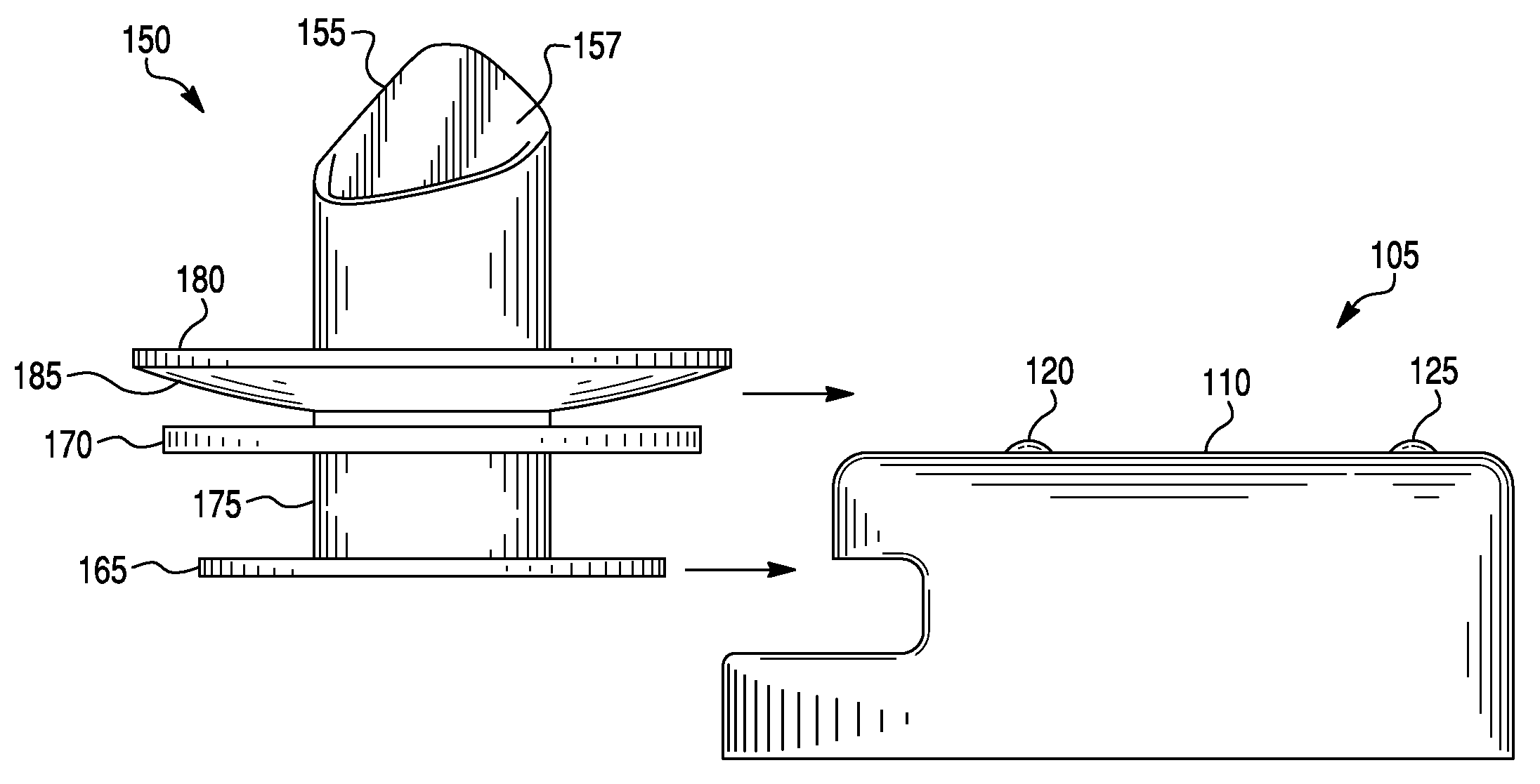
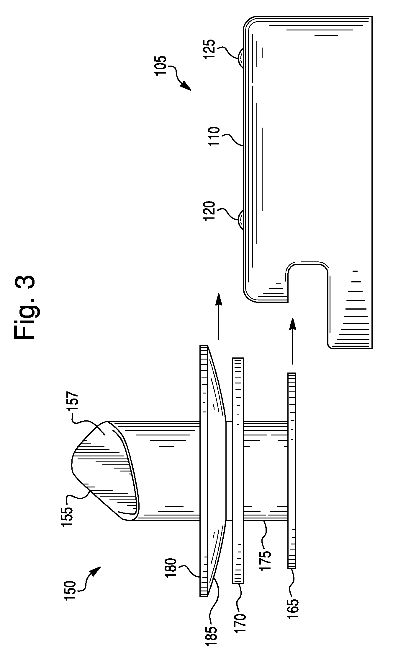
[0029]The disclosed subject matter provides a centering clip device and method for use in a vehicle that allows vehicle components to be firmly affixed to one another so as to minimize rattling, vibration, and / or noise caused by the poor coupling of components. The disclosed subject matter is particularly suited for attaching roofliners or other vehicle panels to a frame or other attachment component within the vehicle. Specifically, the disclosed subject matter facilitates roofliner attachment to the roof frame in those portions of the roof frame that are especially narrow, such as in the area surrounding a sunroof, moonroof, etc.

[0030]Referring to the drawing figures, like reference numerals designate identical or corresponding elements throughout the several figures.

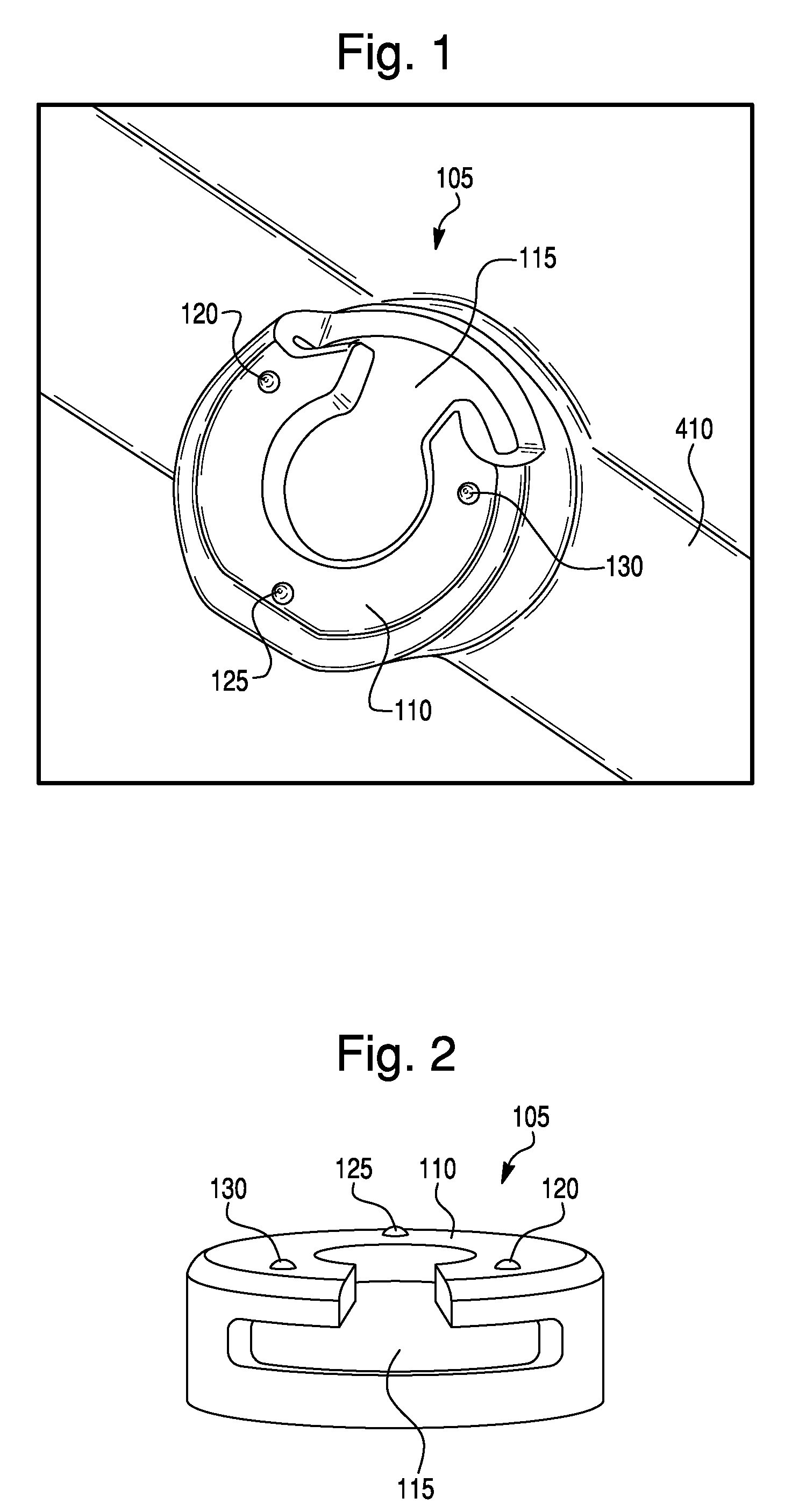
[0031]FIG. 1 illustrates a perspective view of a clip base 105 of a centering clip device according to the principles of the disclosed subject matter. FIG. 1 shows the clip base 105 having a generally circular shape a...


PUM


Abstract

A centering clip device can include a clip base having an opening for receiving a clip. The clip base can have a top surface that has a first bump, a second bump and a third bump all spaced away from each other. A clip can be included that has a substantially elongated body, a bottom flange formed on a bottom end of the clip, a top flange, an annular slot formed between the top flange and the bottom flange, and an umbrella structure. The top flange may also be formed as an umbrella structure having an inclined camming surface formed on its lower surface. The clip base can be configured to releasably engage the clip within the clip base. The camming surface can be biased against the first, second and third bumps to center the clip within the clip base, and permit connection between a first vehicle component, such as a roofliner, to a second vehicle component, such as a roof frame.

Description

[0001]This application and invention claims the priority benefit under 35 U.S.C. §119 of U.S. Provisional Patent Application No. 61 / 042,688 filed on Apr. 4, 2008, which is hereby incorporated in its entirety by reference.BACKGROUND[0002]1. Field[0003]The presently disclosed subject matter relates to fasteners and, more particularly, to an improved fastening structure for securing various vehicle components.[0004]2. Brief Description of the Related Art[0005]A number of different fasteners exist for attaching components, including vehicle components, to support panels. For example, in the automotive industry, various components, such as vehicle interior trim panels, are attached to structural supports which can be made of sheet metal, polymeric materials or composite materials. A common problem with such conventional fastening devices has been that, during assembly, alignment of the fasteners with the apertures provided in the components that are to be attached to can be difficult. As...

Claims


Application Information

Patent Timeline
IPC IPC(8): B60R13/02A44B21/00A44B99/00
CPCB60R13/0206B60R13/0212F16B5/065Y10T24/45099Y10T24/44026Y10T24/30Y10T24/309F16B5/0657
Inventor DONAHUE-YAN, HAITHIYAMASE, SHINICHISEALE, JR., JAMES
Owner HONDA MOTOR CO LTD
Why Eureka
Try Eureka