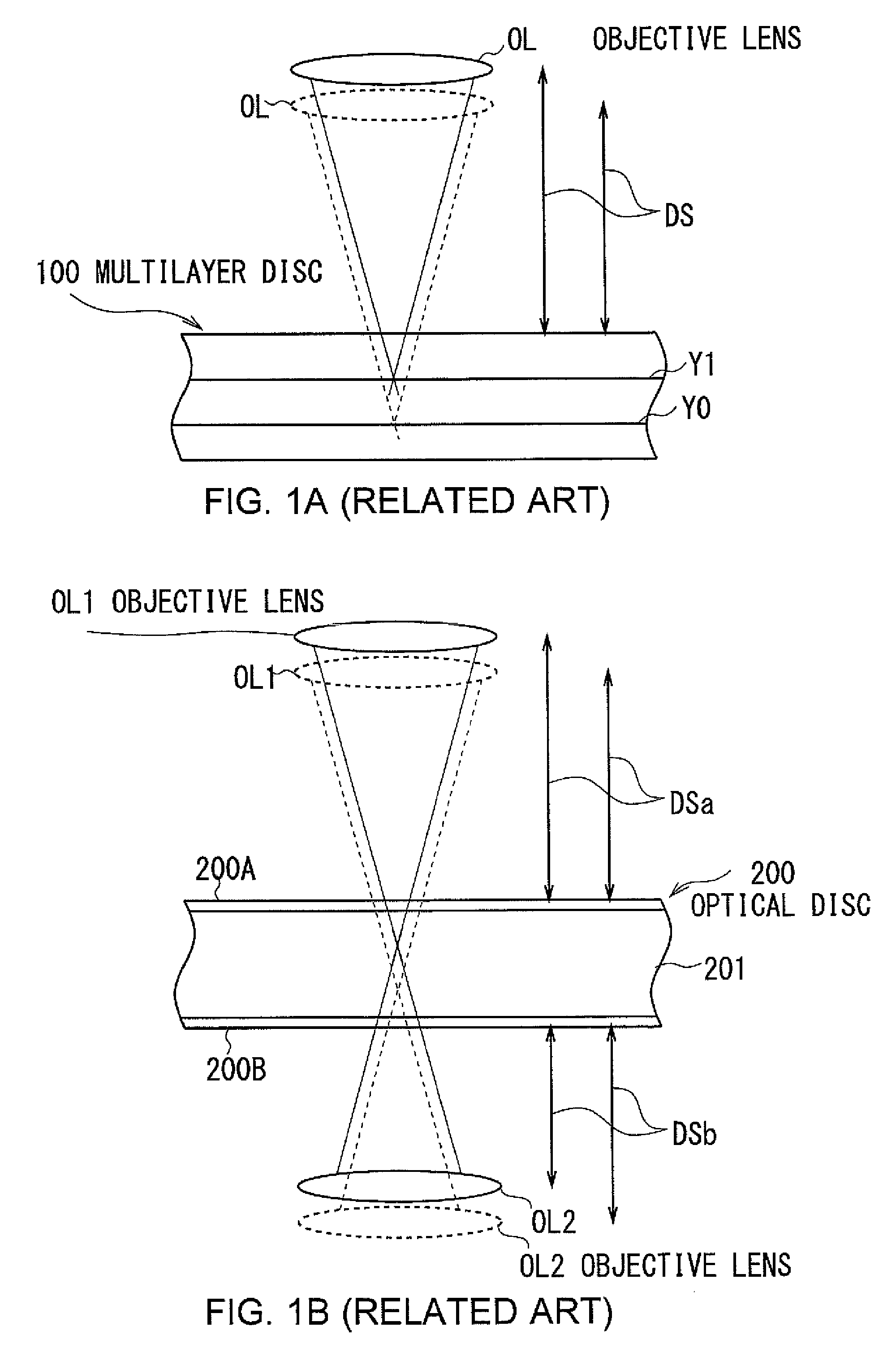
Hologram lens manufacturing apparatus, hologram lens, method of manufacturing hologram lens, information recording apparatus, and information reproducing apparatus
a technology of hologram lens and manufacturing apparatus, which is applied in the direction of optical recording/reproducing/erasing methods, instruments, and record information storage, etc., and can solve the problems of various limitations of the lens
- Summary
- Abstract
- Description
- Claims
- Application Information
AI Technical Summary
Benefits of technology
Problems solved by technology
Method used
Image

Examples
first embodiment
(1) First Embodiment
(1-1) Manufacture of Hologram Lens
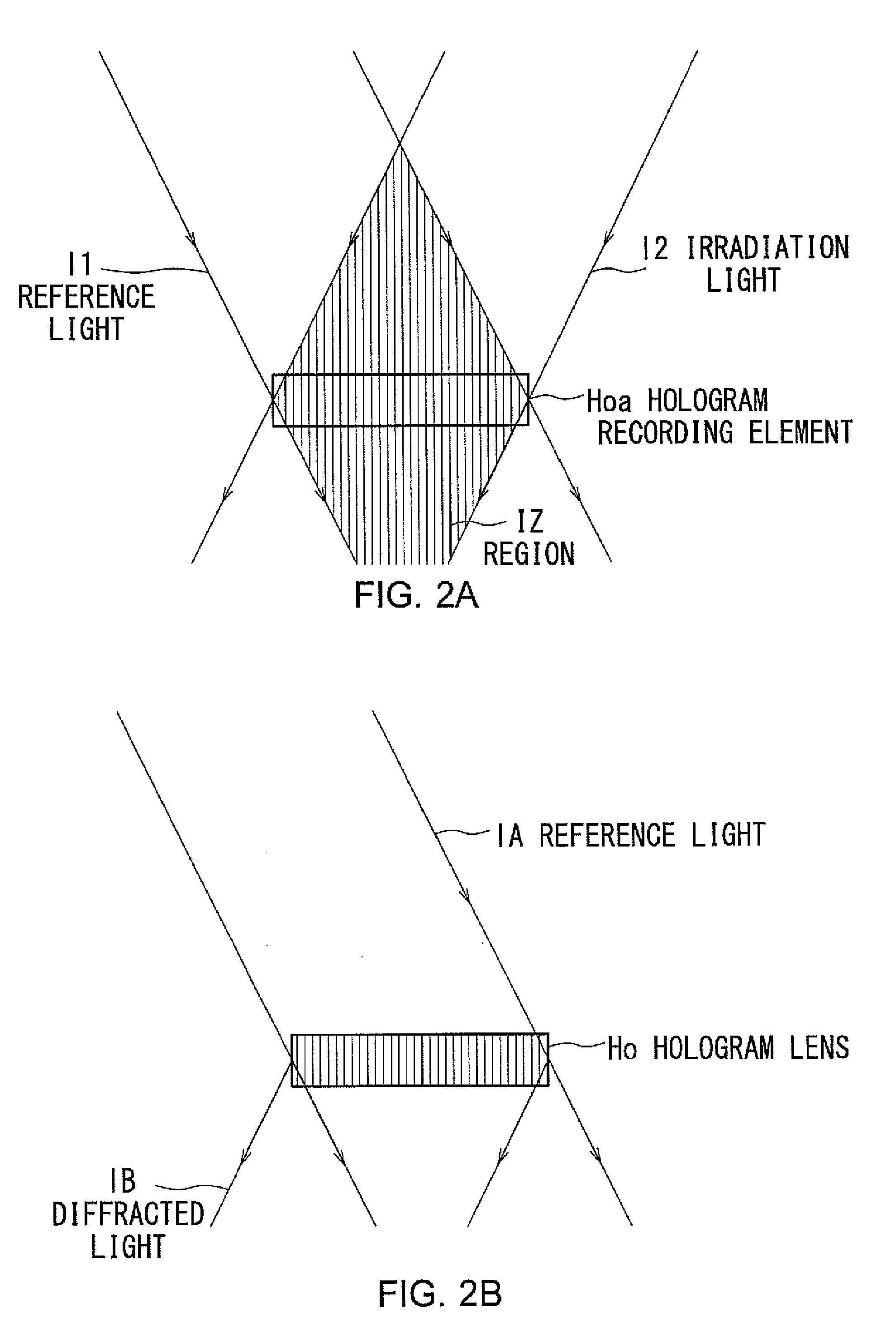
[0064]Description will initially be given of the general principle of a hologram. As shown in FIG. 2A, a hologram element Ho can be created, for example, by recording an interference pattern that occurs when reference light 11 and irradiation light 12 overlap each other, onto a hologram recording element Hoa.
[0065]As shown in FIG. 2B, when this hologram element Ho is irradiated with reference light 1A that has the same properties as those of the reference light 11, a diffracted light beam 1B having the same properties as those of the irradiation light 12 can be produced by diffraction in the hologram element Ho.
[0066]That is, an interference pattern created by the irradiation of two light beams is recorded on the hologram element Ho as a hologram. When this hologram element Ho is irradiated with one of the light beams, it can reproduce the other light beam.
[0067]According to the first embodiment of the present invention, this pri...
second embodiment
(2) Second Embodiment
[0196]FIGS. 13A to 22 show a second embodiment. Parts corresponding to those of the first embodiment shown in FIGS. 1 to 12 will be designated by like reference numerals, and redundant description will be omitted. An optical disc apparatus 20X has the same configuration as that of the first embodiment, and description thereof will thus be omitted.
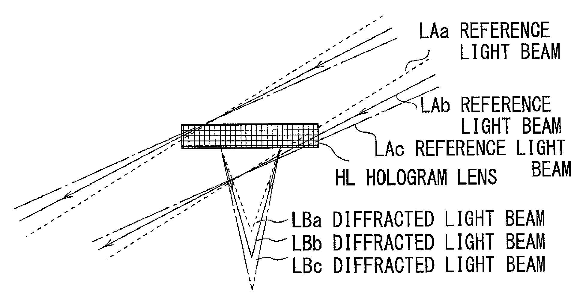
[0197]As shown in FIG. 13A, an optical pickup 39 according to the second embodiment separates a light beam emitted from a single light source into a reference light beam LA and a recording light beam LC. The optical pickup 39 irradiates a hologram lens HL with the reference light beam LA to produce a diffracted light beam LB.
[0198]The optical pickup 39 projects the diffracted light beam LB and the recording light beam LC so that the focal point FB of the diffracted light beam LB and the focal point FC of the recording light beam LC fall on an identical target mark position, thereby creating an interference pattern in th...
third embodiment
(3) Third Embodiment
[0333]FIGS. 25A to 36 show a third embodiment. Parts corresponding to those of the second embodiment shown in FIGS. 13A to 24 will be designated by like reference numerals. Since the configuration of an optical disc apparatus 20Y is the same as in the second embodiment, description thereof will be omitted.
[0334]In the third embodiment, a hologram lens manufacturing apparatus 81 uses a dummy disc 200X having the same characteristics as those of the optical disc 200 instead of the optical disc 200. The hologram lens manufacturing apparatus 81 also uses a light beam that is focused on inside the dummy disc 200X as the reference light beam L1.
[0335]More specifically, as shown in FIGS. 25A and 25B, the hologram lens manufacturing apparatus 81 irradiates a target mark position in the dummy disc 200X with the reference light L1 through an objective lens OL1, projecting the reference light beam L1 from the side of a first surface 200A of the dummy disc 200X. Consequently...
PUM
| Property | Measurement | Unit |
|---|---|---|
| wavelength | aaaaa | aaaaa |
| angle of incidence | aaaaa | aaaaa |
| angle of incidence | aaaaa | aaaaa |
Abstract
Description
Claims
Application Information