

Control apparatus
- Summary
- Abstract
- Description
- Claims
- Application Information
AI Technical Summary
Benefits of technology
Problems solved by technology
Method used
Image

Examples
first embodiment
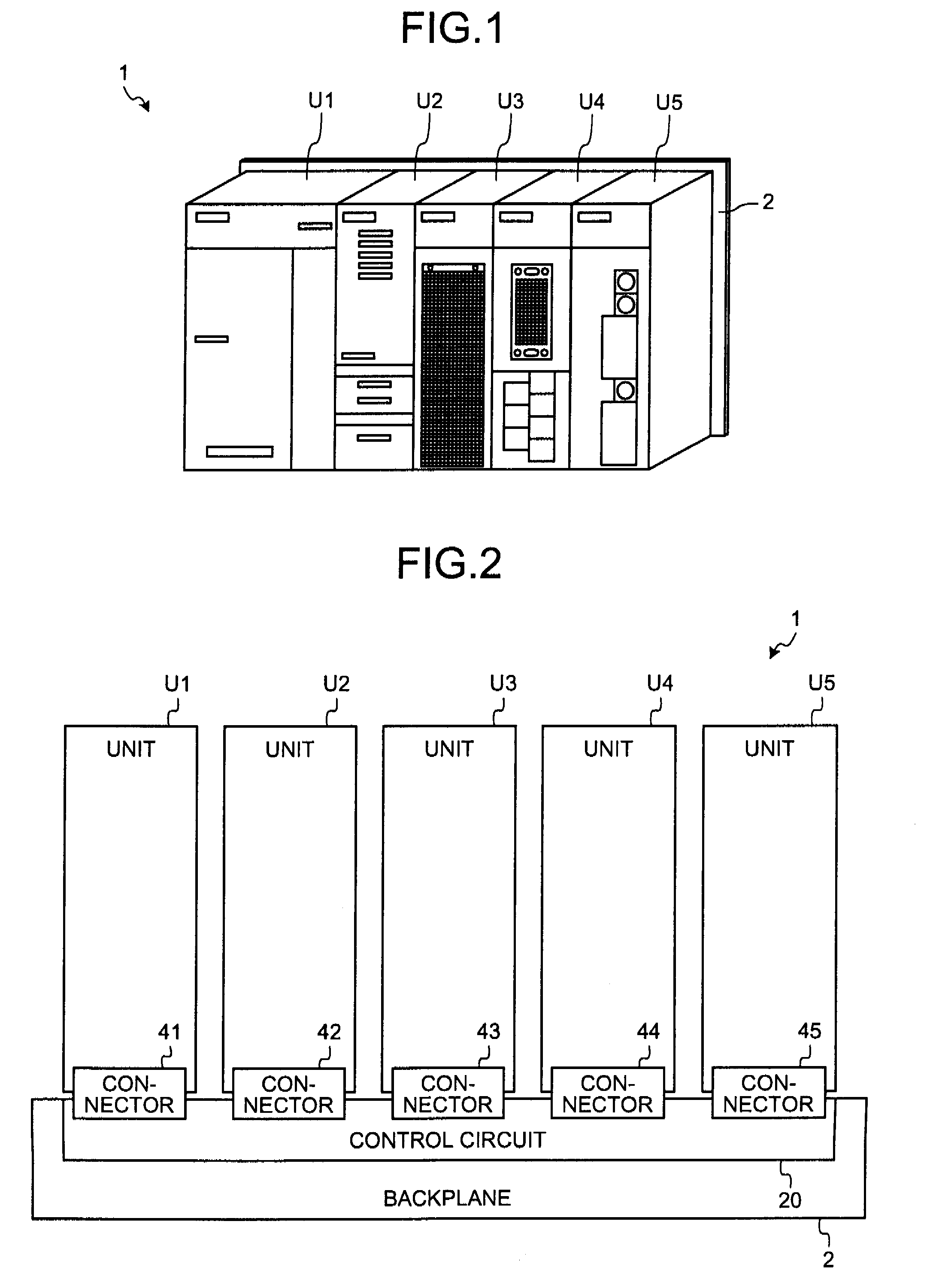
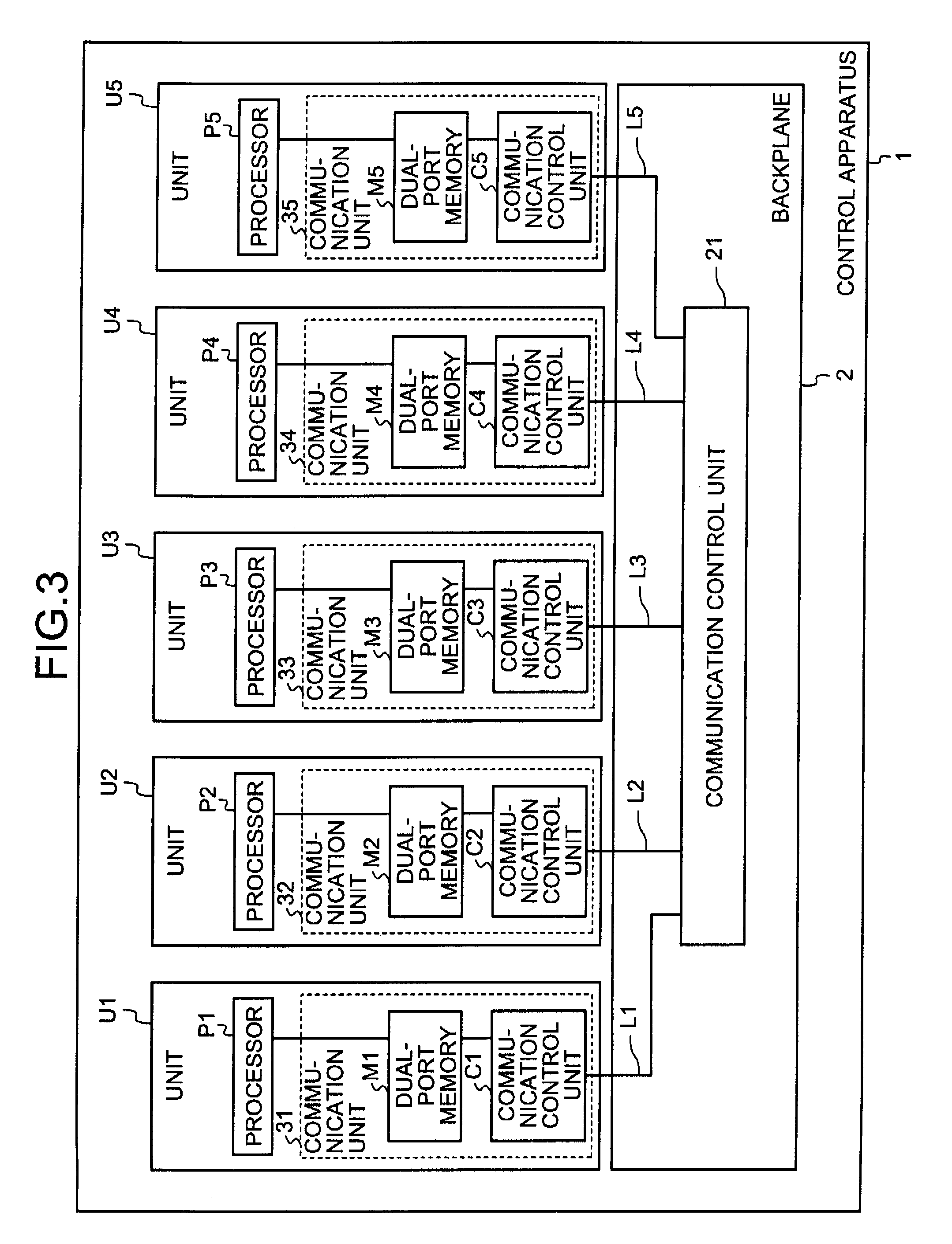
[0038]FIG. 1 is a perspective view of a control apparatus according to the present invention. A control apparatus 1 includes a backplane 2 and one or more building block type units. The control apparatus 1 (precisely, the backplane 2) is configured so that one or more units can be detachably mounted thereon. The control apparatus 1 is configured so that, for example, maximum N units can be mounted thereon (where N is a natural number), and actually M units are mounted on arbitrary locations as needed (where M is a natural number equal to or less than N). In the example shown in FIG. 1, the control apparatus 1 has five units, U1 to U5.
[0039]The backplane 2 is, for example, plate shaped. The backplane 2 includes a plurality of slots (not shown) on the surface thereof for mounting units. The units are mounted on the slots.
[0040]Each of the units U1 to U5 is, for example, rectangular parallelepiped shaped. Each of the units U1 to U5 includes, for example, a control panel, a signal input...
second embodiment
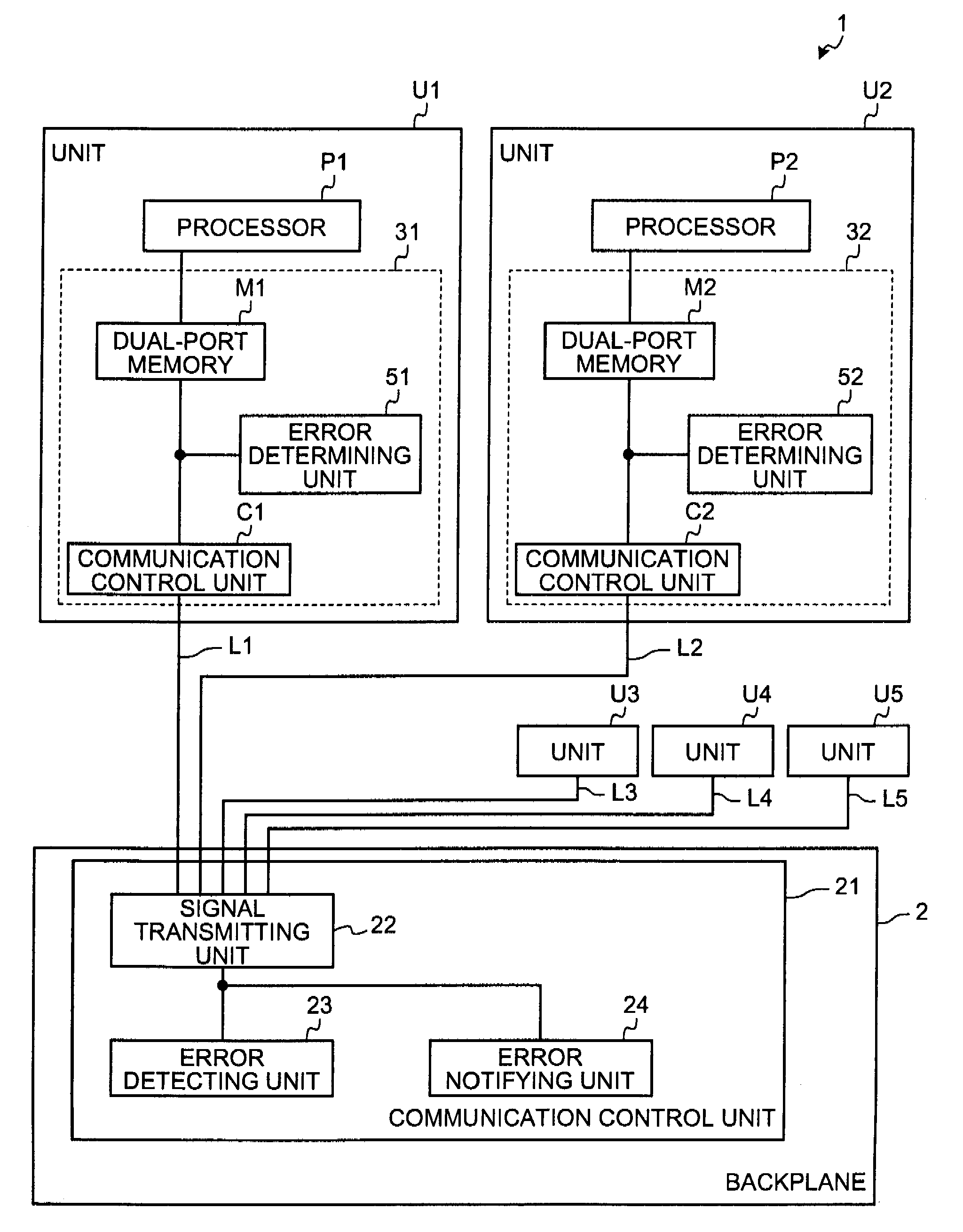
[0083]A second embodiment of the present invention is described below in greater detail with reference to FIGS. 6 to 8. In the second embodiment, the communication control unit 21 in the backplane 2 performs error check on the data received from units U1 to U5, and notifies error check result to the units U1 to U5.
[0084]FIG. 6 is a block diagram of a control apparatus according to the second embodiment. In various elements shown in FIG. 6, similar reference numerals are used to denote elements that achieve functions similar to the control apparatus 1 according to the first embodiment shown. in FIG. 3, and the duplicating descriptions are omitted.
[0085]Typically, the unit U1 performs error check on received data. If only the unit U1 includes a function for detecting a receive error, whether an error occurred in a unit that transmitted the data or a unit that received the data cannot be distinguished. In the second embodiment, by adding an error detecting means and an error notifying ...
third embodiment
[0111]A third embodiment of the present invention is described below in greater detail with reference to FIG. 9. According to the third embodiment, a certain unit, not the backplane 2, includes the communication control unit 21. The communication control unit 21 in the unit is connected to the units U1 to U5 via one-to-one communication lines L1 to L5.
[0112]FIG. 9 is a block diagram of a control apparatus according to the third embodiment. In various elements shown in FIG. 9, similar reference numerals are used to denote elements that achieve functions similar to the control apparatus 1 according to the first embodiment shown in FIG. 3, and the duplicating descriptions are omitted.
[0113]The control apparatus 1 according to third embodiment includes the units U1 to U5, a unit X1, and the backplane 2. The unit X1 includes the communication control unit 21. The communication control unit 21 is connected to the units U1 to U5 via the communication lines L1 to L5. Operations performed by...
PUM
 Abstract
Description
Claims
Application Information