Solar collector and solar heating system using same

a solar collector and solar heating technology, applied in the field of solar collectors, can solve the problems of limited efficiency of the solar collector b>500/b>, inability to adopt thin film technology, and inability to meet the needs of solar collectors,

Active Publication Date: 2009-10-15
TSINGHUA UNIV +1
View PDF24 Cites 10 Cited by
  • Summary
  • Abstract
  • Description
  • Claims
  • Application Information

AI Technical Summary

Problems solved by technology

The traditional solar collector 500 can't adopt the thin film technology because the film is difficult to evaporate on the large area substrate.
As such, the

Method used


Image

  • Solar collector and solar heating system using same
  • Solar collector and solar heating system using same
  • Solar collector and solar heating system using same

Examples


first embodiment

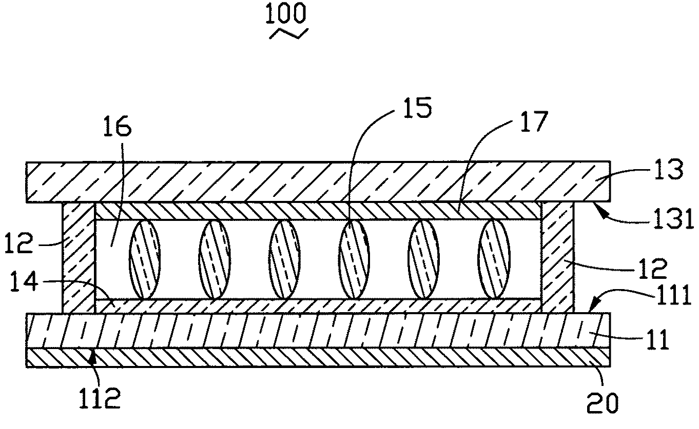
[0019]Referring to FIGS. 1-2, a solar heating system 100 is shown. The solar heating system 100 includes a solar collector 10 and a storage apparatus 20 connected to the solar collector 10. The storage apparatus 20 is configured for storing heat generated by the solar collector 10.

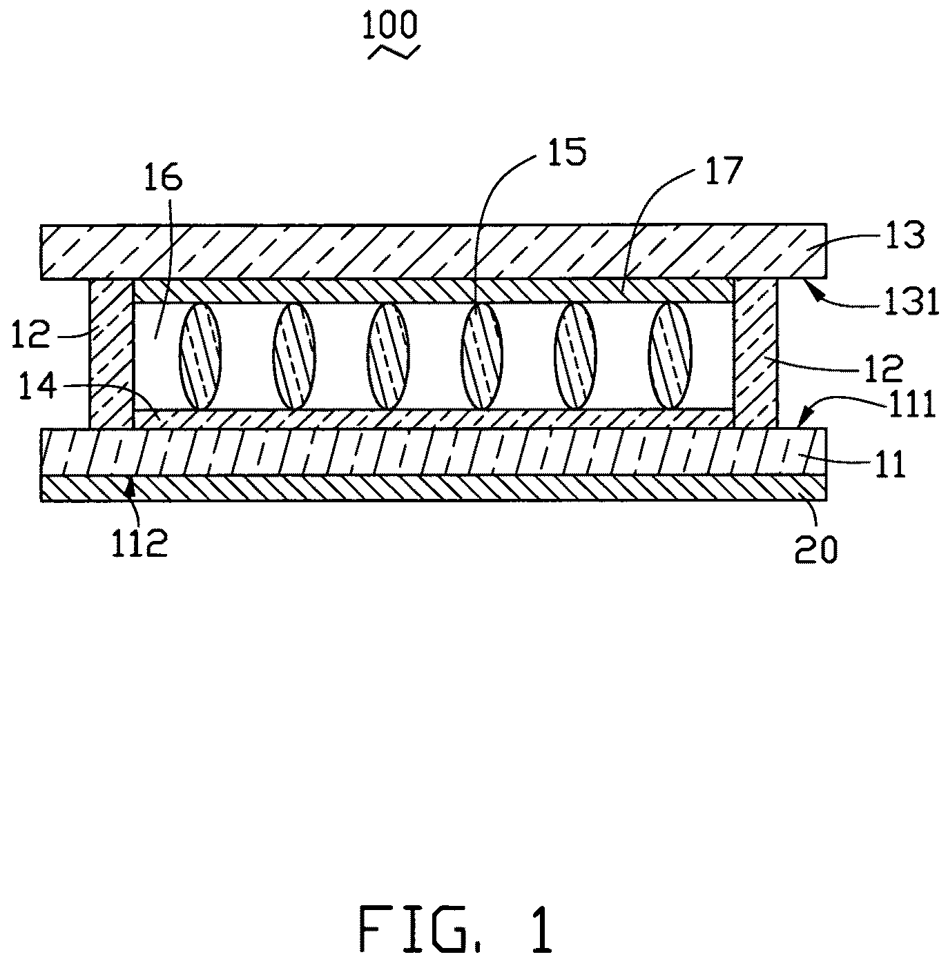
[0020]The solar collector 10 includes a substrate 11, a sidewall 12, a transparent cover 13, a heat-absorbing layer 14 and a number of supporters 15. The substrate 11 has a top surface 111 and a bottom surface 112 opposite to the top surface 111. The transparent cover 13 has a bottom surface 131. The sidewall 12 is mounted on the periphery of the top surface 111 of the substrate 11. The transparent cover 13 is attached on the sidewall 12 opposite to the substrate 11 to form a sealed chamber 16 in cooperation with the sidewall 12 and the substrate 11. The heat-absorbing layer 14 is disposed on the top surface 111 of the substrate 11 and received in the sealed chamber 16.

[0021]The material of the substrate ...

second embodiment

[0026]Referring to FIG. 3, the CNT film can be formed by been drawn from a CNT array, forming a drawn CNT film. The drawn carbon nanotube film includes a plurality of successive carbon nanotubes joined end to end and are aligned substantially in the same direction. The majority of carbon nanotubes are arranged along a primary direction. However, the orientation of some of the nanotubes may vary. Referring to FIG. 4, the drawing carbon nanotube film comprises a plurality of successively oriented carbon nanotube segments 143 joined end-to-end by van der Waals attractive force therebetween. Each carbon nanotube segment 143 includes a plurality of carbon nanotubes 145 parallel to each other, and combined by van der Waals attractive force therebetween. The carbon nanotube segments 143 can vary in width, thickness, uniformity and shape. The carbon nanotubes 145 in the carbon nanotube segment 143 are also oriented along a preferred orientation.

[0027]The drawing carbon nanotube film is dra...

third embodiment

[0028]In a third embodiment, referring to FIG. 5, the CNT film is formed by a flocculation process, forming a flocculated CNT film. The flocculating carbon nanotube film is a carbon nanotube film with a plurality carbon nanotubes therein that are isotropic, uniformly arranged, disordered, and are entangled together. There is a plurality of micropores distributed in the flocculating carbon nanotube film, as such, a specific area of the flocculated carbon nanotube film is extremely large. The thickness of the flocculated carbon nanotube film is ranged from about 1 μm to about 1 mm.


PUM

PropertyMeasurementUnit
Thicknessaaaaaaaaaa
Thicknessaaaaaaaaaa
Thicknessaaaaaaaaaa

Abstract

A solar collector includes a substrate having a top surface and a bottom surface opposite to the upper surface, a sidewall, a transparent cover, and a heat-absorbing layer. The sidewall is arranged on the top surface of the substrate. The transparent cover is disposed on the sidewall opposite to the substrate to form a sealed chamber with the substrate together. The heat-absorbing layer is disposed on the upper surface of the substrate and includes a carbon nanotube structure.

Description

[0001]This application is related to applications entitled, “SOLAR COLLECTOR AND SOLAR HEATING SYSTEM USING SAME”, filed ______ (Atty. Docket No. US19043); “SOLAR COLLECTOR AND SOLAR HEATING SYSTEM USING SAME”, filed ______ (Atty. Docket No. US19045); “SOLAR COLLECTOR AND SOLAR HEATING SYSTEM USING SAME”, filed ______ (Atty. Docket No. US19046); AND “SOLAR COLLECTOR AND SOLAR HEATING SYSTEM USING SAME”, filed ______ (Atty. Docket No. US19448). The disclosures of the above-identified applications are incorporated herein by reference.BACKGROUND[0002]1. Technical Field[0003]The present disclosure relates to a solar collector and, particularly, to a solar collector incorporating carbon nanotubes.[0004]2. Description of Related Art[0005]Generally, solar collectors can be divided into two typical types: pipe solar collectors and flat plate solar collectors. For many applications, it has been demonstrated that the most efficient and least expensive type of solar collector is the flat plate...

Claims


Application Information

Patent Timeline
IPC IPC(8): F24J2/02F24J2/50F24S10/70F24S20/30
CPCF24J2/485F24J2/505Y02E10/40F24J2002/5275F24J2/507F24S80/52F24S70/20F24S2025/011F24S80/54
Inventor LIU, PENGCHEN, PI-JINLIU, LIANGJIANG, KAI-LIFAN, SHOU-SHAN
Owner TSINGHUA UNIV
Why Eureka
Try Eureka