Pneumatic Lift Apparatus

a technology of pneumatic lift and lift tube, which is applied in the direction of chairs, stands/trestles, kitchen equipment, etc., can solve the problems of expensive manufacturing process of polygonal main body and outer tube, and the inability to use pneumatic lift apparatus with a devi

Inactive Publication Date: 2009-10-15
HUANG STEVE
View PDF6 Cites 5 Cited by
  • Summary
  • Abstract
  • Description
  • Claims
  • Application Information

AI Technical Summary

Benefits of technology

[0007]Another feature of this aspect of the present invention is that the restricting means is made of plastics or rubber or a material with plasticity and can be manufactured via inject-molding at a time so that the manufacturing process of the restricting means is quick and economy.

Problems solved by technology

However, such pneumatic lift apparatus is not suitable for use with a device (such as an office chair or leg of a table or things like that) which is not rotatable.
Therefore, another pneumatic lift apparatus comprises a main body and an outer tube, with both the cross-section of the main body and the outer tube being polygonal; nevertheless, an expensive manufacturing process of the polygonal main body and outer tube is still one of the problems.

Method used


Image

  • Pneumatic Lift Apparatus
  • Pneumatic Lift Apparatus
  • Pneumatic Lift Apparatus

Examples


Embodiment Construction

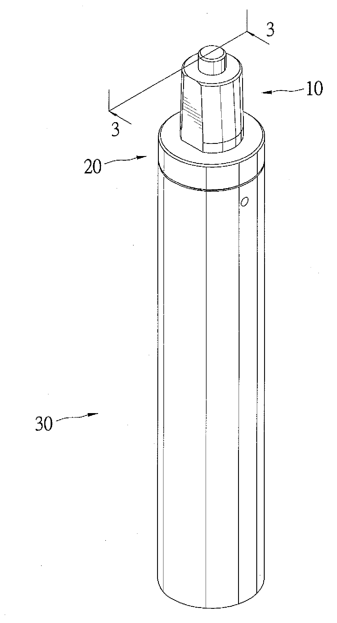
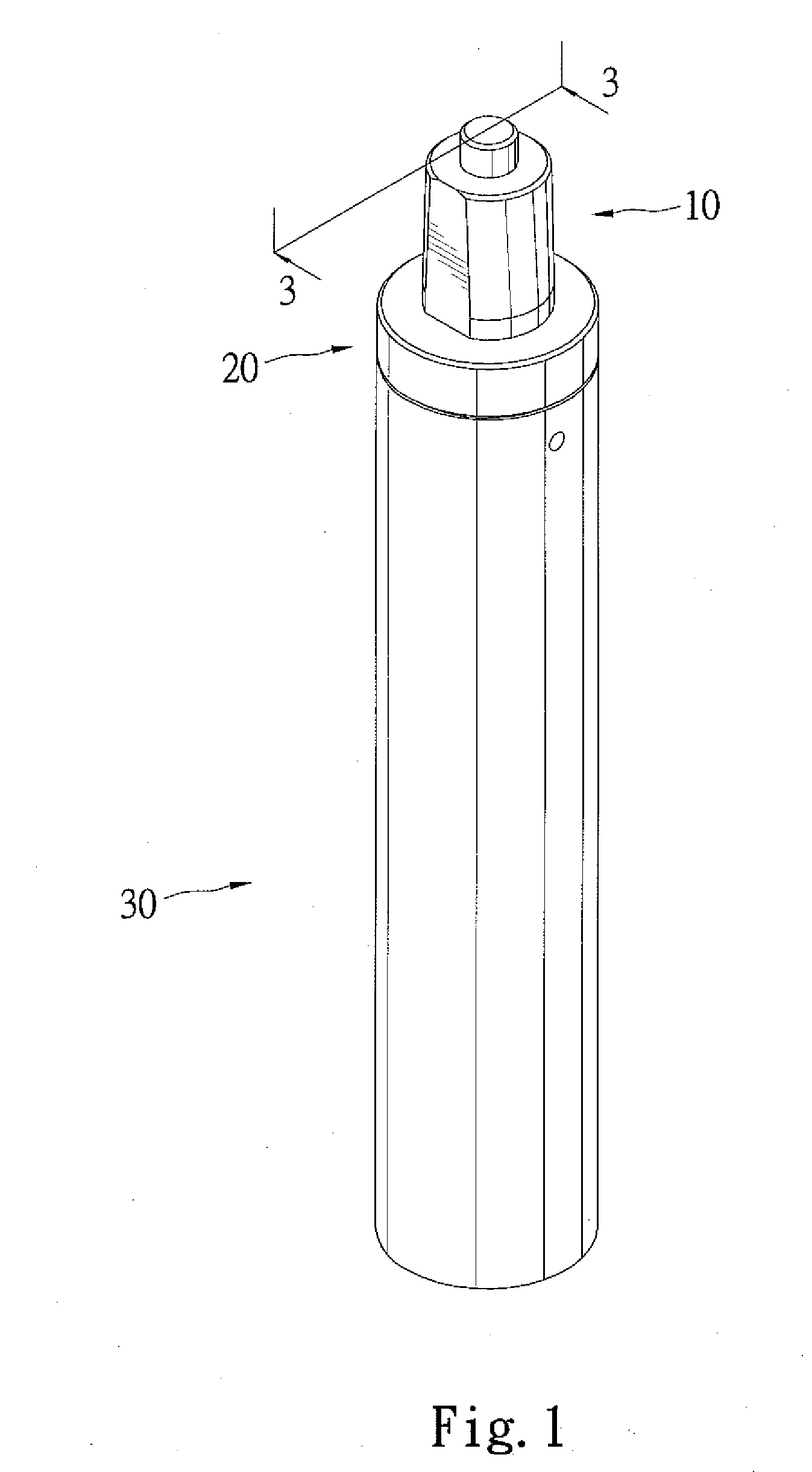
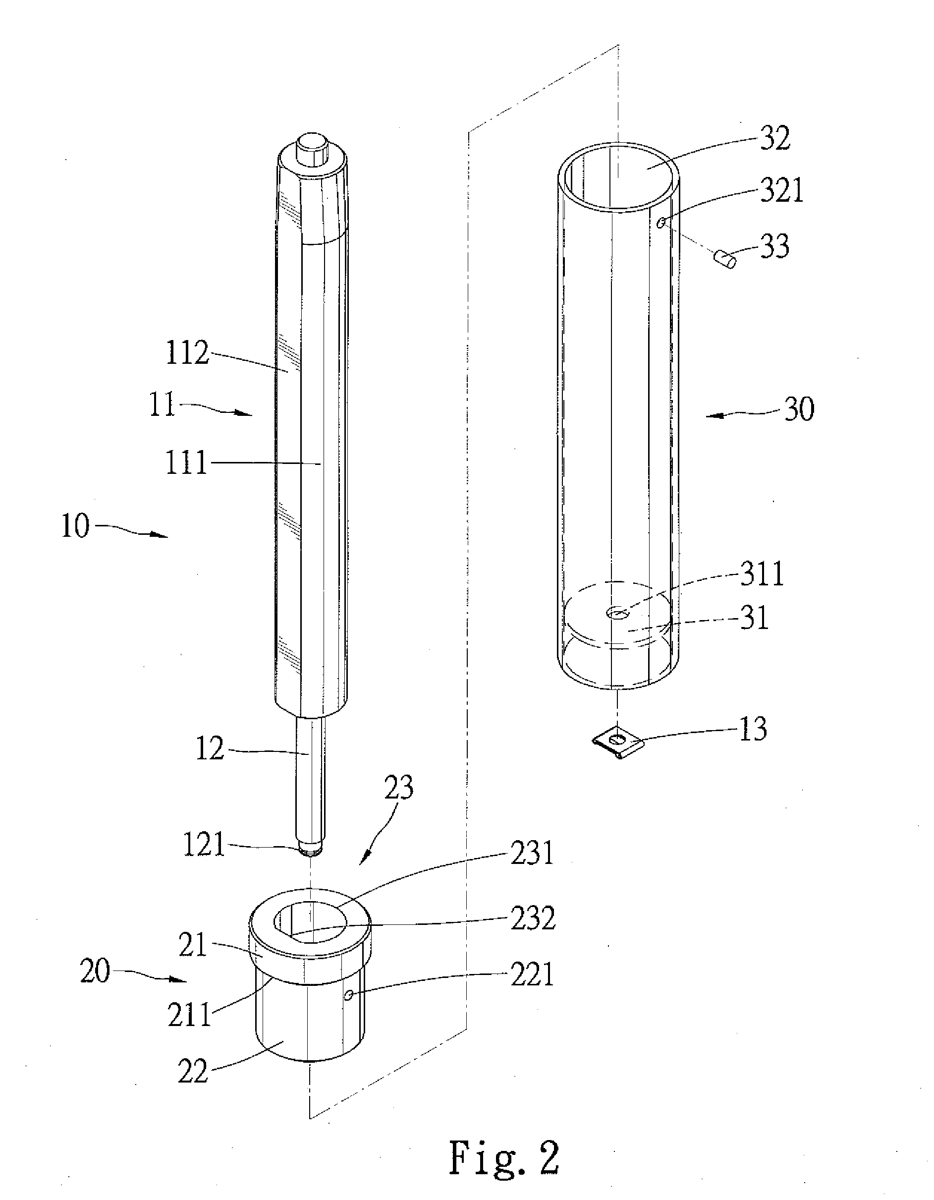
[0023]Referring to FIGS. 1 through 3, a pneumatic lift apparatus in accordance with a first embodiment in the present invention, the pneumatic lift apparatus includes a main body 10, a restricting means 20 and a housing means 30. The length of the main body 10 is adjustable and includes a body tube 11 and a controlling rod 12 slidably received in the body tube 11. The cross-section of the body tube 11 is neither a perfect circle nor a polygon, and the body tube 11 has an arcate portion 111 and a flat portion 112 on the outer circumference thereof, with the arcate portion 111 and the flat portion 112 contiguously connected to each other. A manufacturing process of the body tube 11 is preparing a perfect circle tube and then longitudinally cutting a side of the body tube 11 so that the flat portion 112 is formed. The manufacturing process of the body tube 11 is easy and simple. An end of the controlling rod 12 extends from the body tube 11 and a connected end 121 is defined on the end...


PUM


Abstract

A pneumatic lift apparatus comprises a main body including a body tube, with a cross-section of the body tube being neither a perfect circle nor a polygon; a restricting means slidably mounted on the body tube of the main body, with the body tube restricted not to rotate relative to the restricting means; and a housing means; wherein the restricting means is coupled to an end of the housing means, with the main body inserted through the restricting means and received in the housing means, with the main body fixed in the housing means opposite to the restricting means.

Description

BACKGROUND OF THE INVENTION[0001]1. Field of the Invention[0002]The invention relates to an elevation apparatus for a device such as an office chair or leg of a table or things like that. More particularly, this invention relates to a pneumatic lift apparatus to hold a device, such as an office chair or a leg of a table or things like that, for a user to use while either sitting at the device or standing near the device.[0003]2. Description of the Related Art[0004]Pneumatic lift apparatus are usually adapted for elevation adjustment of a device such as an office chair or a leg of a table or things like that. A prior pneumatic lift apparatus as disclosed in Taiwan Patent No 579776 comprises a main body and an outer tube, with both the cross-section of the main body and the outer tube being perfect circle. The main body is rotably received in the outer tube, so that the device connected to the main body can be driven to rotate. However, such pneumatic lift apparatus is not suitable fo...

Claims


Application Information

Patent Timeline
Patent Type & Authority Applications(United States)
IPC IPC(8): A47C3/20
CPCA47C3/30
Inventor HUANG, STEVE
Owner HUANG STEVE
Why Eureka
Try Eureka