
Low-cost high precision twisting measuring device

a measuring device and low-cost technology, applied in the field of hand tools, can solve the problems of unnecessary power supply, and achieve the effects of low cost, high precision and simple structur

Active Publication Date: 2006-08-15
HSIEH CHIH CHING
View PDF8 Cites 4 Cited by
  • Summary
  • Abstract
  • Description
  • Claims
  • Application Information

AI Technical Summary

Benefits of technology

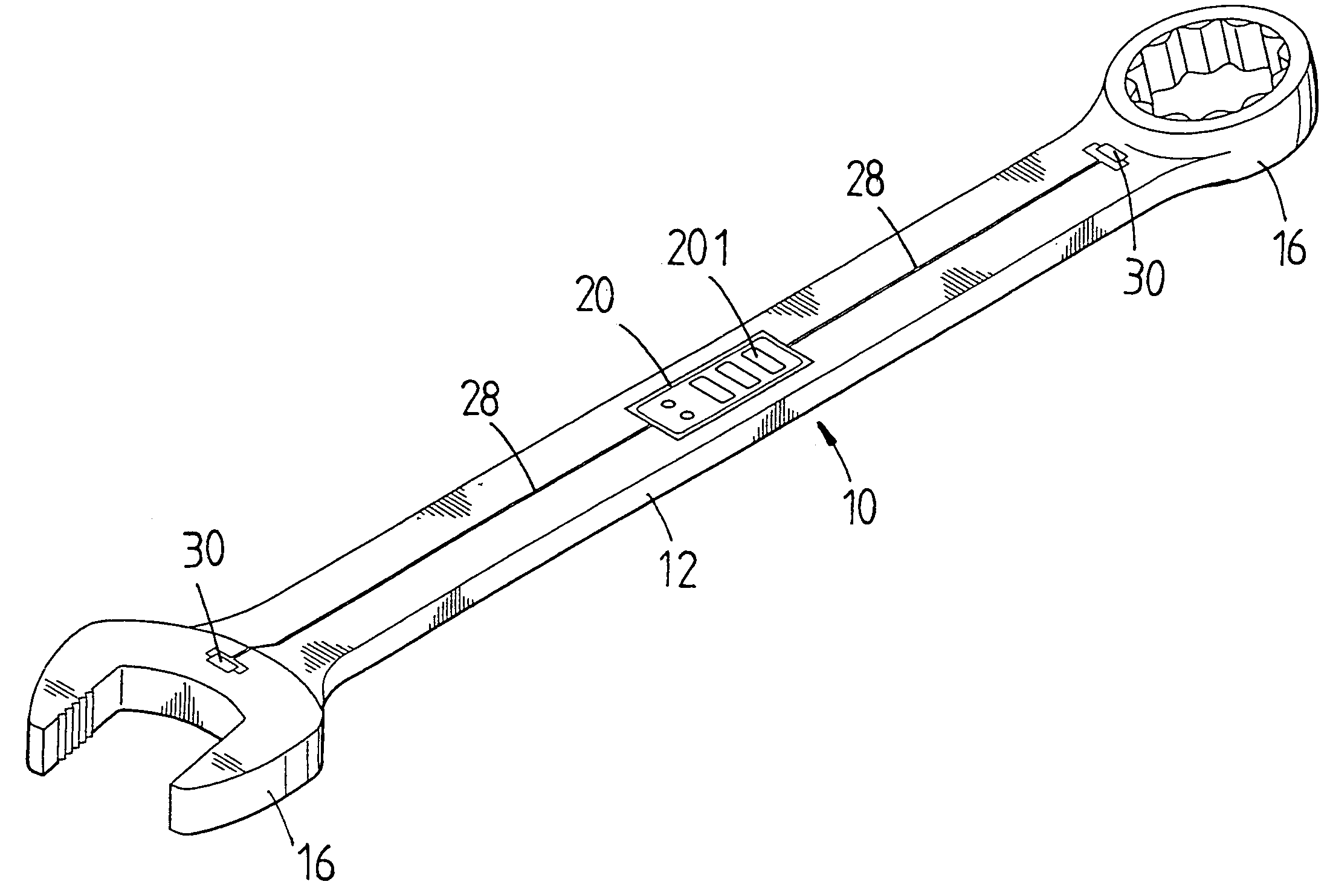
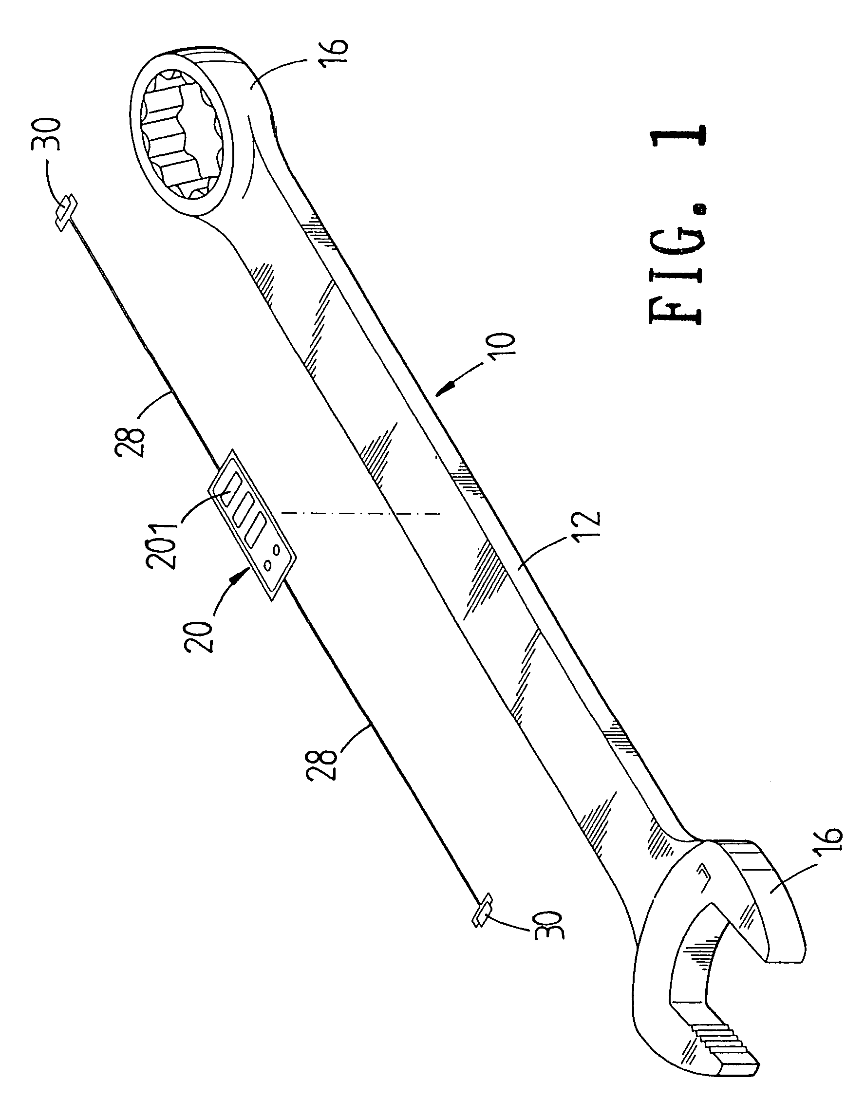
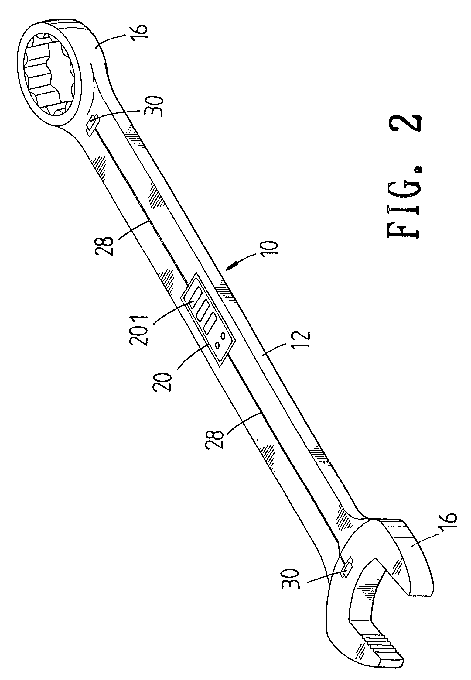
"The present invention provides a low-cost high precision twisting measuring device that is easy to manufacture and has high precision. It uses a piezoelectric ceramic sensor that does not require a power supply and is not confined by the size of the device. The sensor converts dynamic power into electric power and sends it to a display for visualization. This invention is a better alternative to prior art strain gauges and can be used in various applications such as spanner measurements."

Problems solved by technology

Moreover it is unnecessary to have any power supply.

Method used


Image

  • Low-cost high precision twisting measuring device
  • Low-cost high precision twisting measuring device
  • Low-cost high precision twisting measuring device

Examples


second embodiment

[0026]With reference to FIG. 4, the second embodiment about the low-cost high precision twisting measuring device of the present invention is illustrated. This embodiment is similar to former one, and thus those identical to the former one will not described further. Only the differences of the two are described.

[0027]In this embodiment, the piezoelectric ceramic sensor 30 is applied to an adjustable spanner 40. The piezoelectric ceramic sensor 30 is located in a fixed jaw 42 of the adjustable spanner 40, which can still achieve the object of high precision of the sensing of twisting force.

third embodiment

[0028]Furthermore, referring to FIG. 5, the present invention is illustrated. This embodiment is similar to former one, and thus those identical to the former one will not described further. Only the differences of the two are described.

[0029]In the third embodiment, the piezoelectric ceramic sensor 30 is applied to a sleeve form spanner 50, which can still achieve the object of high precision of the sensing of twisting force.

[0030]Furthermore, referring to FIG. 6, the fourth embodiment of the present invention is illustrated. This embodiment is similar to former one, and thus those identical to the former one will not described further. Only the differences of the two are described. In the third embodiment, the piezoelectric ceramic sensor 30 is applied to a ratchet spanner 60, which can still achieve the object of high precision to the sensing of twisting force.


PUM


Abstract

A low-cost high precision twisting measuring device comprising a tool body; the tool body comprises a handle having a display; at least one end of the handle having a driving portion; each connection between the handle and each driving portion having a piezoelectric ceramic sensor; the piezoelectric ceramic sensor being connected to the display through a conductor; the piezoelectric ceramic sensor serving to convert mechanical power due to operation of the spanner into electric power with a form of voltage signals; the voltage signal being transferred to the display through the conductor.

Description

FIELD OF THE INVENTION[0001]The present invention relates to hand tools, and in particular to a piezoelectric ceramic sensor is not confined by the size and thus the recess in the tool body for receiving the piezoelectric ceramic sensor can be smaller than those used for the prior art strain gauge. The piezoelectric ceramic sensor acts without needing power supply for converting dynamic power into electric power.BACKGROUND OF THE INVENTION[0002]Currently, there are many hand tools need to know the twisting force of the tool applied to an object so that the user can well control the operation of the tool. Thereby there are many tools which are equipped with the twisting force measuring tool. In one prior art, a measuring rod interconnected to the driving head so that when the driving head is driven, the measuring rod will displace so that the twisting force can be got from the displacement of the measuring rod.[0003]In another prior art, springs and rolling shafts are embedded into t...

Claims


Application Information

Patent Timeline
Patent Type & Authority Patents(United States)
IPC IPC(8): B25B23/14
CPCB25B23/1425
Inventor HSIEH, CHIH-CHING
Owner HSIEH CHIH CHING
Learn More