Stand alone lamp filament preheat circuit for ballast

a technology of filament heating circuit and ballast, which is applied in the direction of transit-tube circuit elements, circuit elements of cathode-ray/electron beam tubes, circuit elements of structural circuit elements, etc., can solve the limit on the degree to which the filament heating power may be reduced, and the lamp life is considered to be significantly reduced

Inactive Publication Date: 2009-10-15
OSRAM SYLVANIA INC
View PDF13 Cites 6 Cited by
  • Summary
  • Abstract
  • Description
  • Claims
  • Application Information

AI Technical Summary

Problems solved by technology

On the other hand, instant start operation usually results in considerably lower lamp life than preheat operation.
An acknowledged drawback of this approach is a limit on the degree to which filament heating power may be reduced once the lamp ignites and begins to operate; a detailed discussion of the difficulties with this approach is provided in the “Background of the Invention” section of U.S. Pat. No. 5,998,930, the relevant portions of which are incorporated herein by reference.
Because this approach is difficult and / or costly to implement in ballasts having self-oscillating type inverters, it is usually employed only in ballasts having driven type inverters.
This approach has the further disadvantage of producing a significant amount of “glow current” through the lamp immediately prior to ignition.
Glow current is generally considered to negatively impact the useful life of the lamp.
This approach tends to be rather costly to implement, especially in ballasts that power multiple lamps because multiple switching circuits are required (i.e., one for each filament or each pair of parallel-connected filaments).
All of the aforementioned approaches are largely limited in function to filament heating and do not provide any separate benefits, such as automatic relamping capability or prevention of the high voltages, currents, and power dissipation that generally occurs following lamp removal or failure.
Because ballasts that implement these approaches generally require separate, dedicated circuitry in order to accommodate relamping and protect the ballast from damage due to lamp removal or failure, the resulting ballasts tend to be functionally and structurally complex.

Method used


Image

  • Stand alone lamp filament preheat circuit for ballast
  • Stand alone lamp filament preheat circuit for ballast
  • Stand alone lamp filament preheat circuit for ballast

Examples


Embodiment Construction

[0016]In one embodiment, the present invention is an independent fluorescent lamp filament preheating circuit. It is contemplated that this circuit would operate independently of any normal ballast operation and would be compatible with most if not all types of ballasts. For example, this circuit may be used with in conjunction with instant start self-oscillating topology ballasts to convert the ballast into a program start ballast. Alternatively, or in addition, this circuit may be used for lamp filament heating during dimming operation of a ballast.

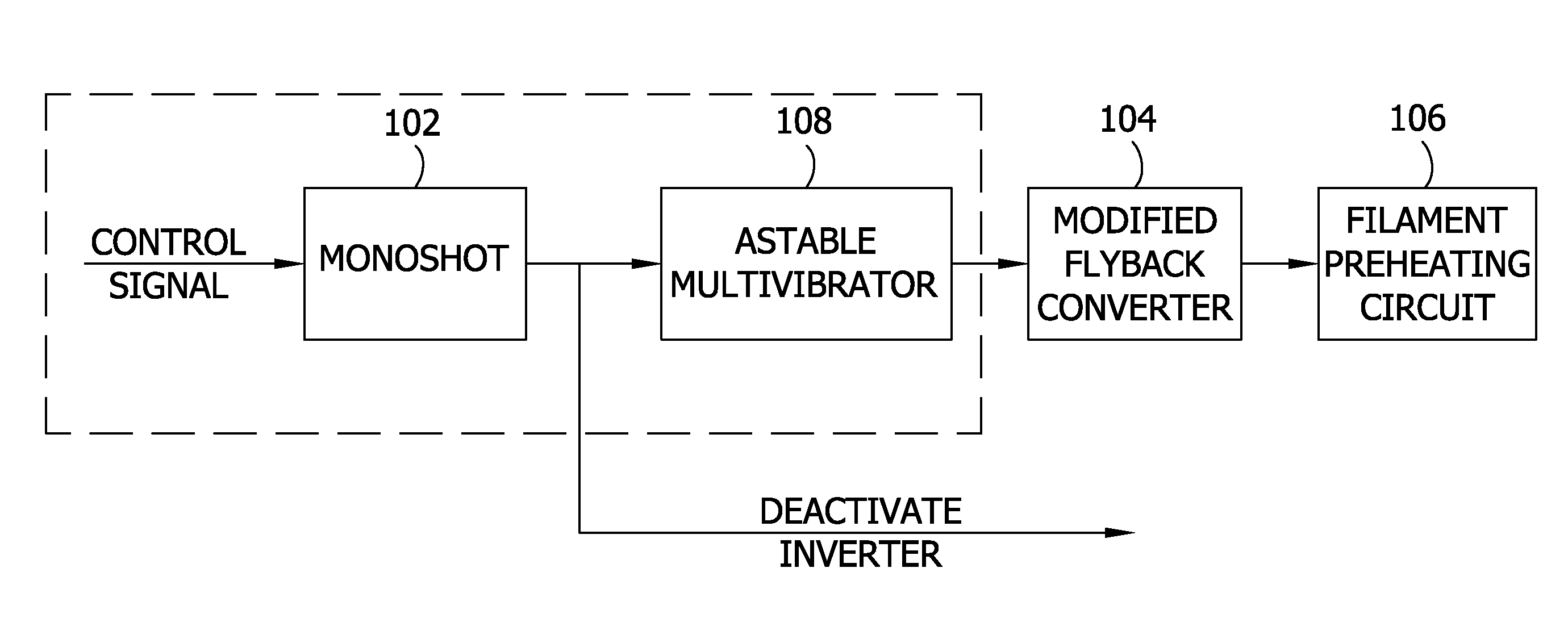
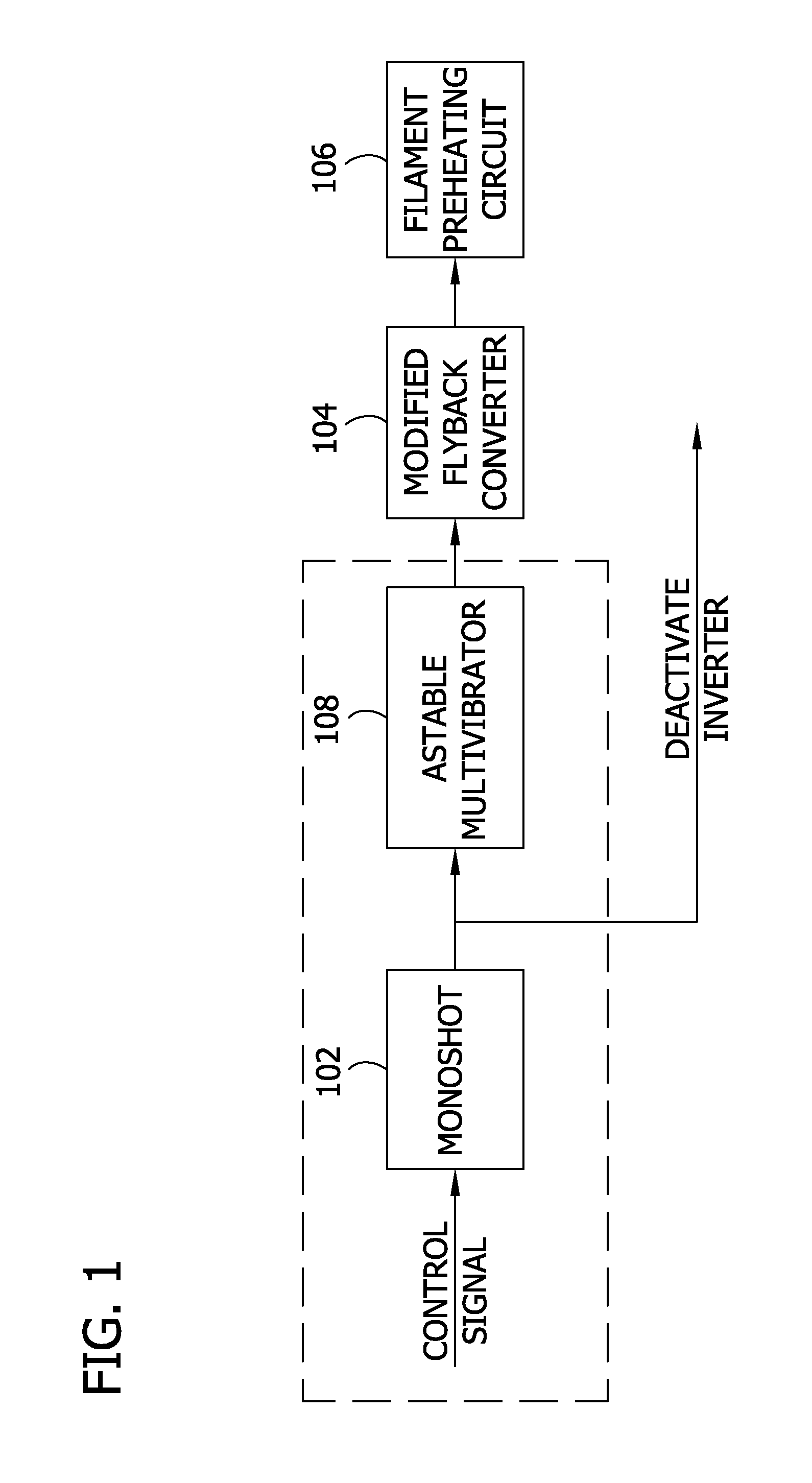
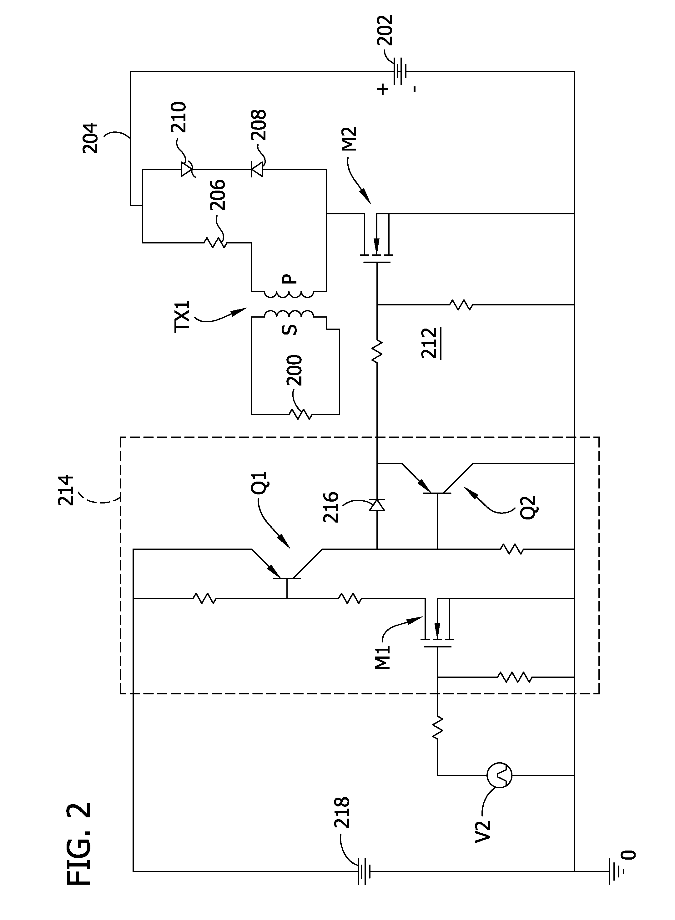
[0017]FIG. 1 is a block diagram of one embodiment of a filament preheating circuit according to the invention. The half bridge self-oscillation aspects of normal lamp operation are not shown in FIG. 1 and FIG. 2. A filament preheating circuit 106 is energized by a flyback converter 104 which has been modified. When power to a de-energized ballast is provided, a control signal indicative of the switched ON power activates a monoshot circ...


PUM


Abstract

A lamp filament preheating circuit using modified flyback topology which gives pulsating AC in the secondary of the flyback transformer. The circuit may be controller based or implemented by a monoshot and astable multivibrator. A self-oscillation, parallel resonant current fed half bridge inverter circuit may include an arc sensing circuit.

Description

FIELD OF THE INVENTION[0001]The present invention generally relates to a lamp filament preheating circuit and, in particular, a controller based independent fluorescent lamp filament preheating circuit and, optionally, circuit for anti-arcing.BACKGROUND OF THE INVENTION[0002]Electronic ballasts for gas discharge lamps are often classified into two groups according to how the lamps are ignited—preheat and instant start. In preheat ballasts, the lamp filaments are preheated at a relatively high level (e.g., 7 volts peak) for a limited period of time (e.g., one second or less) before a moderately high voltage (e.g., 500 volts peak) is applied across the lamp in order to ignite the lamp. In instant start ballasts, the lamp filaments are not preheated, so a higher starting voltage (e.g., 1000 volts peak) is required in order to ignite the lamp. It is generally acknowledged that instant start operation offers certain advantages, such as the ability to ignite the lamp at a lower ambient te...

Claims


Application Information

Patent Timeline
IPC IPC(8): H01J7/44
CPCH05B41/295
Inventor KALUGUMALAI, ANTONY NEETHI MANICKAMGUPTA, ASHISH KUMAR
Owner OSRAM SYLVANIA INC
Why Eureka
Try Eureka