Vessel pulse wave measurement system conducting vessel pulse wave measurement by obtaining pulsation waveform of blood vessel

a technology of pulse wave measurement and blood vessel, which is applied in the direction of catheters, instruments, angiography, etc., can solve the problems of inability to accurately perform vessel pulse wave measurement, the attachment state may change during measurement, and the measurement cannot always maintain a stable state, etc., and achieves a simple configuration

Active Publication Date: 2012-11-15
ACT MEDICAL SERVICE
View PDF2 Cites 23 Cited by
  • Summary
  • Abstract
  • Description
  • Claims
  • Application Information

AI Technical Summary

Benefits of technology

[0031]In addition, a second object of the present invention is to solve the above-described problems and to provide a vessel pulse wave measurement system capable of detecting abnormal respiration using the above-described vessel pulse wave measurement system, with a simpler configuration and higher accuracy than those of the prior art.
[0032]Further, a third object of the present invention is to provide a vessel pulse wave measurement system capable of performing calibration to convert a blood pressure value voltage of a vessel pulse wave signal to a blood pressure value, using the above-described vessel pulse wave measurement system, with a simpler configuration and higher accuracy than those of the prior art.

Problems solved by technology

However, a living body, which is a target for measuring pulsation of a blood vessel, such as a person to be measured, does not always maintain a stable state during measurement.
In addition, if the attachment state of the light emitting element and the light receiving element is incomplete, then the attachment state may change during measurement.
If the pulsation waveform thus shifts from the measurement range, then accurate vessel pulse wave measurement cannot be performed.
However, the apparatuses according to the prior art disclosed in the above-described Patent Documents 1 to 3 have such a problem that the apparatuses do not work almost at all on the measurement scene because of frequent occurrence of the case in which the apparatuses cannot obtain pulsation waveform data due to that the operation of obtaining pulsation of a blood vessel often becomes an unstable state,
In addition, the abnormal respiration detection apparatus according to the prior art disclosed in the Patent Document 4 has such a problem that the accuracy of detection of abnormal respiration is still low, in addition to the above-described problem.

Method used


Image

  • Vessel pulse wave measurement system conducting vessel pulse wave measurement by obtaining pulsation waveform of blood vessel
  • Vessel pulse wave measurement system conducting vessel pulse wave measurement by obtaining pulsation waveform of blood vessel
  • Vessel pulse wave measurement system conducting vessel pulse wave measurement by obtaining pulsation waveform of blood vessel

Examples


Embodiment Construction

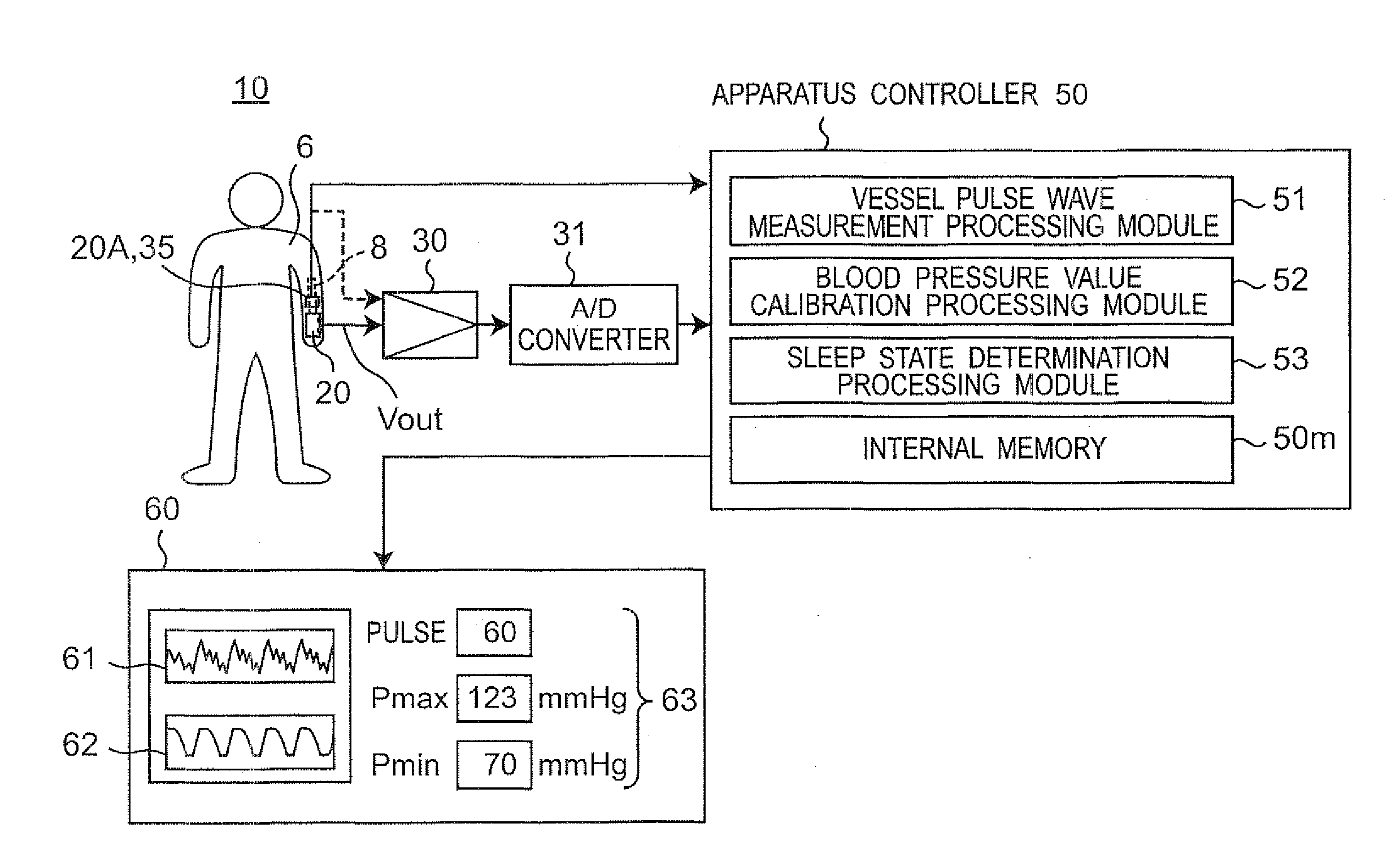
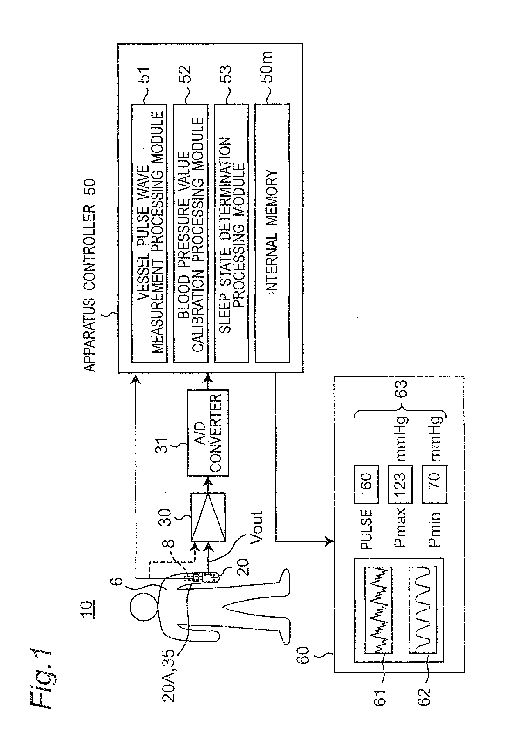
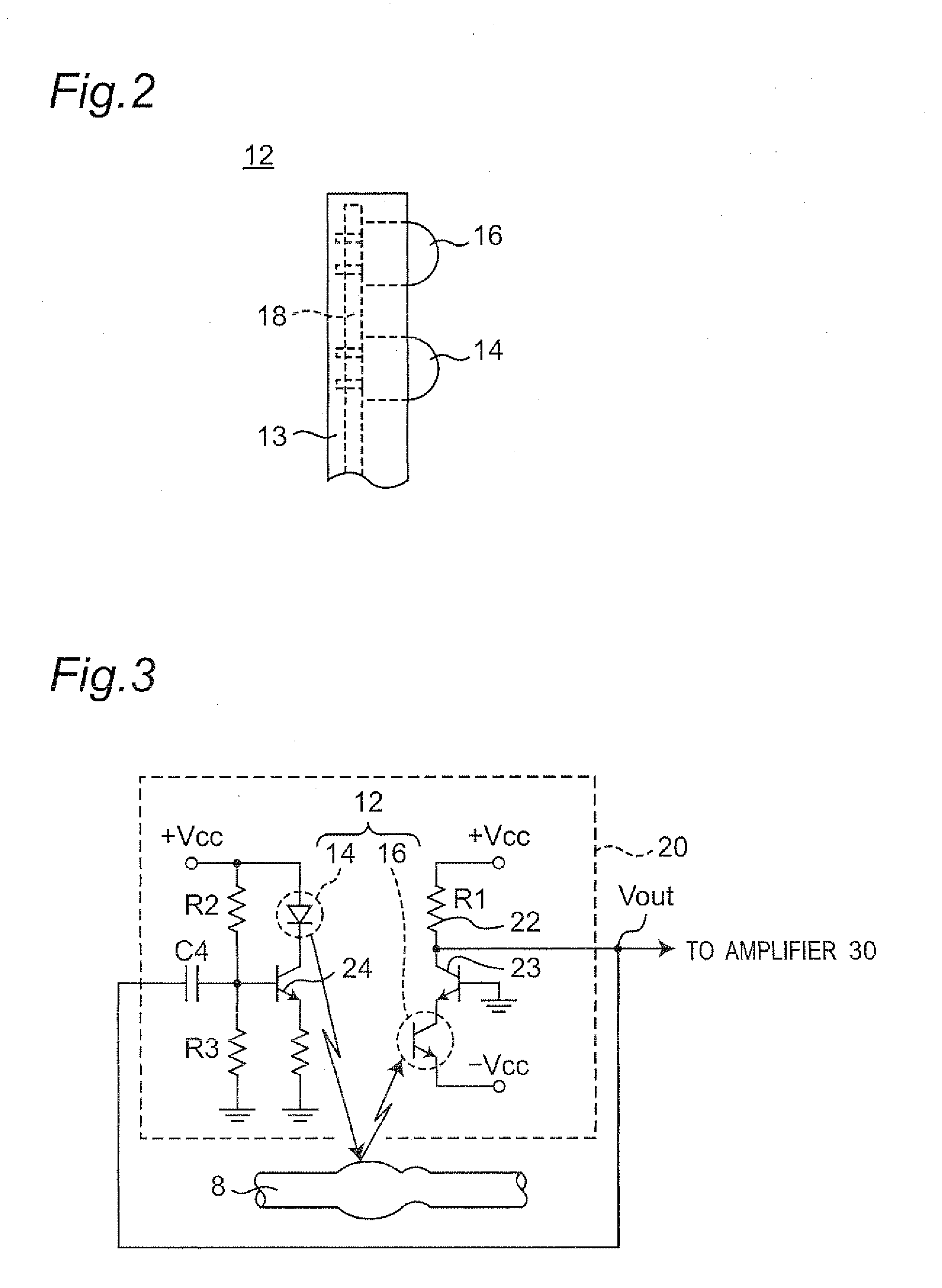
[0078]Embodiments according to the present invention will be described below with reference to the drawings. It is noted that in each of the following embodiments, like components are denoted by the same reference characters. Although a pulse wave of a human blood vessel will be described in the following as a measurement target, the target can be any as long as the target is a pulse wave of a living body blood vessel and thus animals or the like other than humans can be used as the target. In addition, although in the following, as vessel pulse wave measurement, measurement of a pulse, a maximum blood pressure, and a minimum blood pressure will be described, any other measurement may be performed using a pulsation waveform of a blood vessel. For example, a volume corresponding to the volume of blood flow may be measured from an integral value of a pulse waveform and measurement for evaluating blood vessel flexibility from a differential value of a pulsation waveform may be performe...


PUM


Abstract

A vessel pulse wave measurement system performs vessel pulse wave measurement using an optical probe circuit provided with an optical probe including a light emitting element and a light receiving element, a drive circuit, and a detection circuit. A measurement device directly and synchronously feeds back an electrical signal from the optical probe to the drive circuit as a drive signal to generate a self-oscillation signal from the detection circuit, and measures the self-oscillation signal as a vessel pulse wave signal. A controller controls an operating point of at least one of the detection circuit and the drive circuit such that the self-oscillation signal substantially reaches a maximum level thereof.

Description

[0001]This is a continuation application based on PCT application No. PCT / JP2011 / 080339 as filed on Dec. 27, 2011, which claims priority to Japanese patent application No. JP 2011-012106 as filed Jan. 24, 2011, the contents of which are incorporated herein by reference.BACKGROUND OF THE INVENTION[0002]1. Field of the Invention[0003]The present invention relates to a vessel pulse wave measurement system, and more particularly, to a vessel pulse wave measurement system that performs vessel pulse wave measurement by obtaining a pulsation waveform (hereinafter, referred to as a pulse wave) of a blood vessel using a light emitting element and a light receiving element.[0004]2. Description of the Related Art[0005]For techniques for evaluating properties of a material, a method using an oscillation has been known. Patent Document 1 discloses a method of converting phase change to frequency change, taking into account that in the difference in the properties of the material, a change in the...

Claims


Application Information

Patent Timeline
Patent Type & Authority Applications(United States)
IPC IPC(8): A61B5/024A61B5/021A61B6/00
CPCA61B5/02125G01L9/0007A61B5/7203A61B5/02225A61B5/02438A61B5/4809A61B5/7221A61B5/02108A61B5/4812A61B5/4818A61B5/7278A61B5/6824A61B5/6826A61B5/0082A61B5/0245A61B5/0285
Inventor TAKENOSHITA, SEIICHICHIBA, SHINTAROHATA, YUTAKAWIEDEMANN, TOKUKOANNOH, HIROMICHIYAGI, ASAKOTAKAHASHI, SHINICHIHANDA, FUKUTOYAJIMA, TOSHIKUNI
Owner ACT MEDICAL SERVICE
Why Eureka
Try Eureka