Solenoid valve

a solenoid valve and valve body technology, applied in the direction of valve operating means/release devices, mechanical equipment, transportation and packaging, etc., can solve the problems of >, and the solenoid valve b>1/b> is liable to generate self-oscillation, and achieve the effect of suppressing self-oscillation

Active Publication Date: 2008-08-19
JTEKT CORP
View PDF7 Cites 22 Cited by
  • Summary
  • Abstract
  • Description
  • Claims
  • Application Information

AI Technical Summary

Benefits of technology

[0009]Accordingly, it is a primary object of the present invention to provide an improved solenoid valve capable of securing the damping effect of operating oil against a spool valve and a plunger even during the operation in the atmosphere over a long period of time and hence, of suppressing the self oscillation.
[0011]With this construction, since the upper part of the annular oil groove communicates with the outside of the insertion bore through the drain passage, the annular oil groove is able to store the operating oil to the height of the upper part thereof and hence, to reserve the operation oil in the spring chamber communicating therewith through the respiration passage. Thus, when the plunger is attracted to be axially moved in dependence on an electromagnetic force exerted thereon as the coil is energized to control the controlled pressure from the output port and when the spool valve is moved together with the plunger against the resilient force of the spring, the spool valve is prevented from generating the self oscillation by the damping effect of the operating oil reserved in the spring chamber.
[0012]Where the state continues for a long time that the plunger and hence, the spool valve are kept stopped at one stroke end thereof as a result of applying the maximum control current to the coil in order to keep the controlled pressure from the output port high, the operating oil under the highest controlled pressure which is supplied from the output port to the feedback port flows into the spring chamber through a clearance between the spool valve and the valve hole, is then supplied from the spring chamber through the respiration passage to the annular oil groove, and is further discharged to the outside of the insertion bore through the drain passage. Also where the state continues for a long time that the spool valve is kept stopped at the other stroke end thereof as a result of applying the minimum control current to the coil in order to keep the controlled pressure from the output port low, the operating oil under the lowest controlled pressure supplied to the feedback port flows into the spring chamber through the clearance between the spool valve and the valve hole. Accordingly, it can be realized to continuously supply and reserve the operating oil into the spring chamber even where the state continues for a long time that the solenoid valve is exposed to the atmosphere with the spool valve stopped in an initial state. Thus, when moved from the stop state, the spool valve can advantageously be prevented from generating the self oscillation by the damping effect of the operating oil reserved in the spring chamber.

Problems solved by technology

Therefore, the damping effect of the operating oil against the movement of the plunger 17 cannot be achieved, whereby the solenoid valve 1 is liable to generate the self oscillation.

Method used


Image

  • Solenoid valve
  • Solenoid valve
  • Solenoid valve

Examples


second embodiment

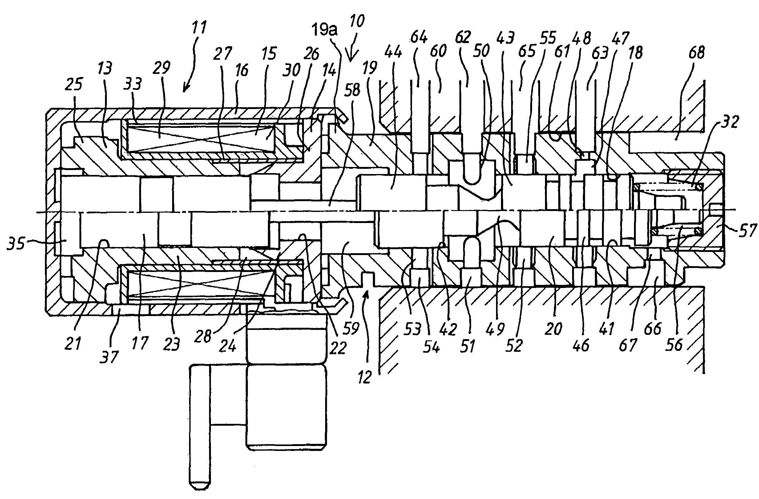
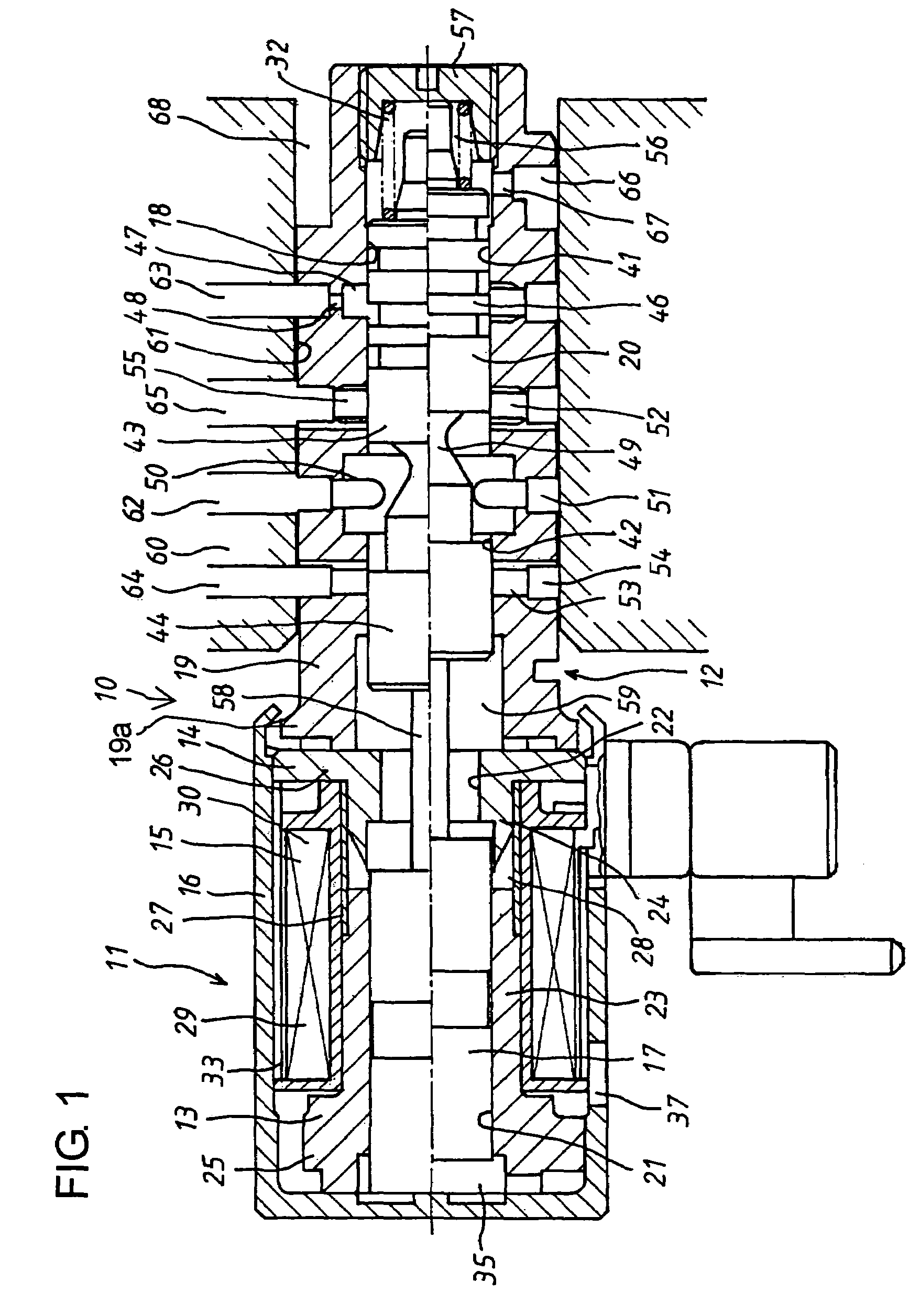
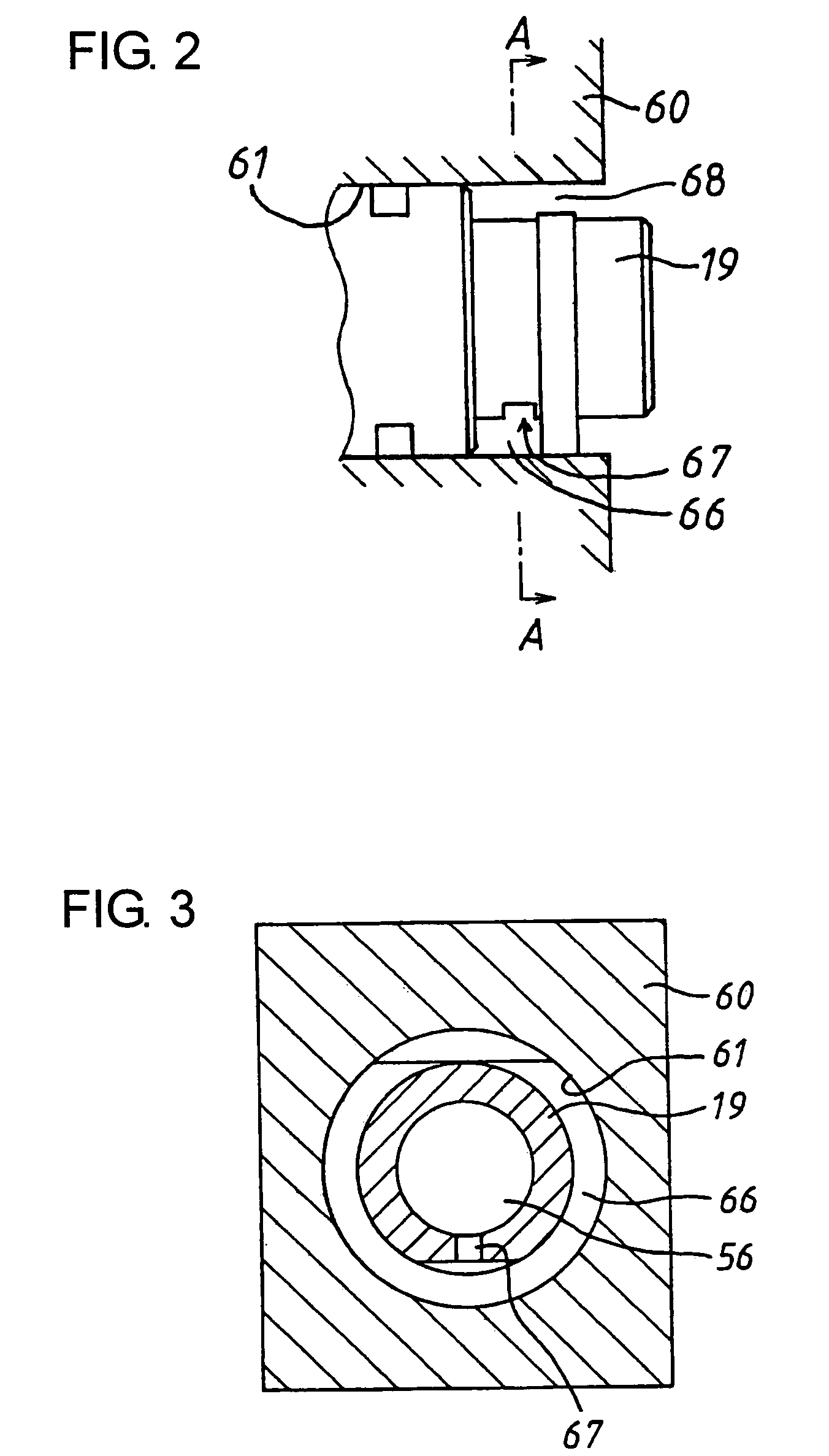
[0039]Next, description will be made regarding a solenoid valve 10 of the normally closed type in a second embodiment according to the present invention. The second embodiment features making the communication of the main drain port 54 with the annular oil groove 66 as compared with the solenoid valve 10 in the foregoing first embodiment shown in FIG. 1. Specifically, as shown in FIG. 4, the external surface of the sleeve 19 has formed thereon a communication groove 69 which makes the main drain port 54 and the annular oil groove 66 communicate with each other.

[0040]As described earlier with reference to FIG. 1, the main drain port 54 communicates with the supply port 51 through the annular recess 50 when the minimum control current is applied to the coil 29, and with the increase of the control electric current to the coil 29, the second land portion 44 in cooperation with the annular recess 53 gradually decreases the flow path area between the output port 51 and the main drain por...

third embodiment

[0041]Next, description will be made regarding a solenoid valve 10 of the normally open type in a third embodiment according to the present invention. Being the same as that in the first embodiment, the construction of the solenoid section 11 in the third embodiment is therefore omitted for the sake of brevity.

[0042]Referring now to FIGS. 5(a) and 5(b), a sleeve 119 is inserted into an insertion bore 161 which is formed horizontally in a valve body 160. The valve body 160 is contained in an oil pan (not shown) for an electronically controlled automatic transmission (not shown), and the insertion bore 161 is made as an open bore which passes through the valve body 160 to open outside at opposite ends thereof. A valve hole 118 having a first valve hole 141 and a second valve hole 142 which are different in diameter is formed in the sleeve 119 in axial alignment with the through hole 22 of the core 14. A spool valve 120 slidably fitted in the valve hole 118 is formed thereon with first...

fourth embodiment

[0049]Next, description will be made regarding a solenoid valve 10 of the normally open type in a fourth embodiment according to the present invention. The solenoid valve 10 in the fourth embodiment differs from that in the third embodiment in that the annular recess 152 for the main drain port 154 is made to communicate with the spring chamber 156 instead of making the main drain passage 164 communicate with the annular oil groove 166 through the lead passage 170. Specifically, as shown in FIG. 6, a communication groove 175 is formed on the external surface of the sleeve 119 to extend from over the annular recess 152 for the main drain port 154 to over the spring chamber 156, and holes 176 and 177 are formed at opposite ends of the communication groove 175, wherein the hole 176 communicates with the annular recess 152, while the hole 177 communicates with the spring chamber 156.

[0050]Thus, where the state continues for a long time that the plunger 17 and hence, the spool valve 120 ...


PUM


Abstract

In a solenoid valve 10, an annular oil groove 66 is formed at a portion corresponding to a spring chamber 56 on the external surface of a sleeve 19, a drain passage 68 is formed to make an upper part of the annular oil groove 66 communicate with the outside of an insertion bore 61, and a throttle hole 67 is provided at a lower part of the annular oil groove 66 for making the annular oil groove 66 communicate with the spring chamber 56. Since the annular oil groove 66 communicates with the outside of the insertion bore 61 at its upper part through the drain passage 68, it can be realized to store the operating oil to the height of the upper part of the annular oil groove 66, so that the operating oil can be reserved in the spring chamber 56 which communicates with the annular oil groove through the throttle hole 67. Further, the operating oil is supplied from a feedback port 48 next to the spring chamber 56 through a clearance between the spool valve 19 and a valve hole 18. Thus, the solenoid valve 10 is able to secure the damping effect of the working oil on the spool valve 19 and a plunger 17 and to suppress the self oscillation even while being operated in the atmosphere for a long time.

Description

[0001]This application is based on and claims priority under 35 U.S.C. 119 with respect to Japanese Application No. 2004-300238 filed on Oct. 14, 2004.BACKGROUND OF THE INVENTION[0002]1. Field of the Invention[0003]The present invention relates to a solenoid valve in which a spool valve is operated by the axial movement of a plunger corresponding to electric current applied to a coil.[0004]2. Discussion of the Related Art[0005]In solenoid valves of the type that a plunger is moved by a magnetic attraction force upon energization of a coil of a linear solenoid and that the areas of fluid paths opening to a valve hole are controlled by a spool valve which is moved within the valve hole as a result of the plunger being moved, variation is made volume of a rear end chamber to which the plunger enters its rear end portion upon movement thereof. It is described in Japanese unexamined, published patent application No. 2002-310322 to provide a respiration passage so that the operating oil c...

Claims


Application Information

Patent Timeline
Patent Type & Authority Patents(United States)
IPC IPC(8): F15B13/043
CPCF16K31/0689F16K31/0613Y10T137/86614Y10T137/8671
Inventor SEGI, MASAYASUZUKI, MIKIOSUZUKI, MASARUTAKANISHI, KOICHIFUJITA, KAORI
Owner JTEKT CORP
Why Eureka
Try Eureka