
Control apparatus and method for vehicle equipped with internal combustion engine

a technology of control apparatus and internal combustion engine, which is applied in the direction of machines/engines, fluid gearings, process and machine control, etc., can solve the problems of internal combustion engine oscillations more violent, and deterioration of driving comfor

Inactive Publication Date: 2003-02-13
TOYOTA JIDOSHA KK
View PDF2 Cites 30 Cited by
  • Summary
  • Abstract
  • Description
  • Claims
  • Application Information

AI Technical Summary

Benefits of technology

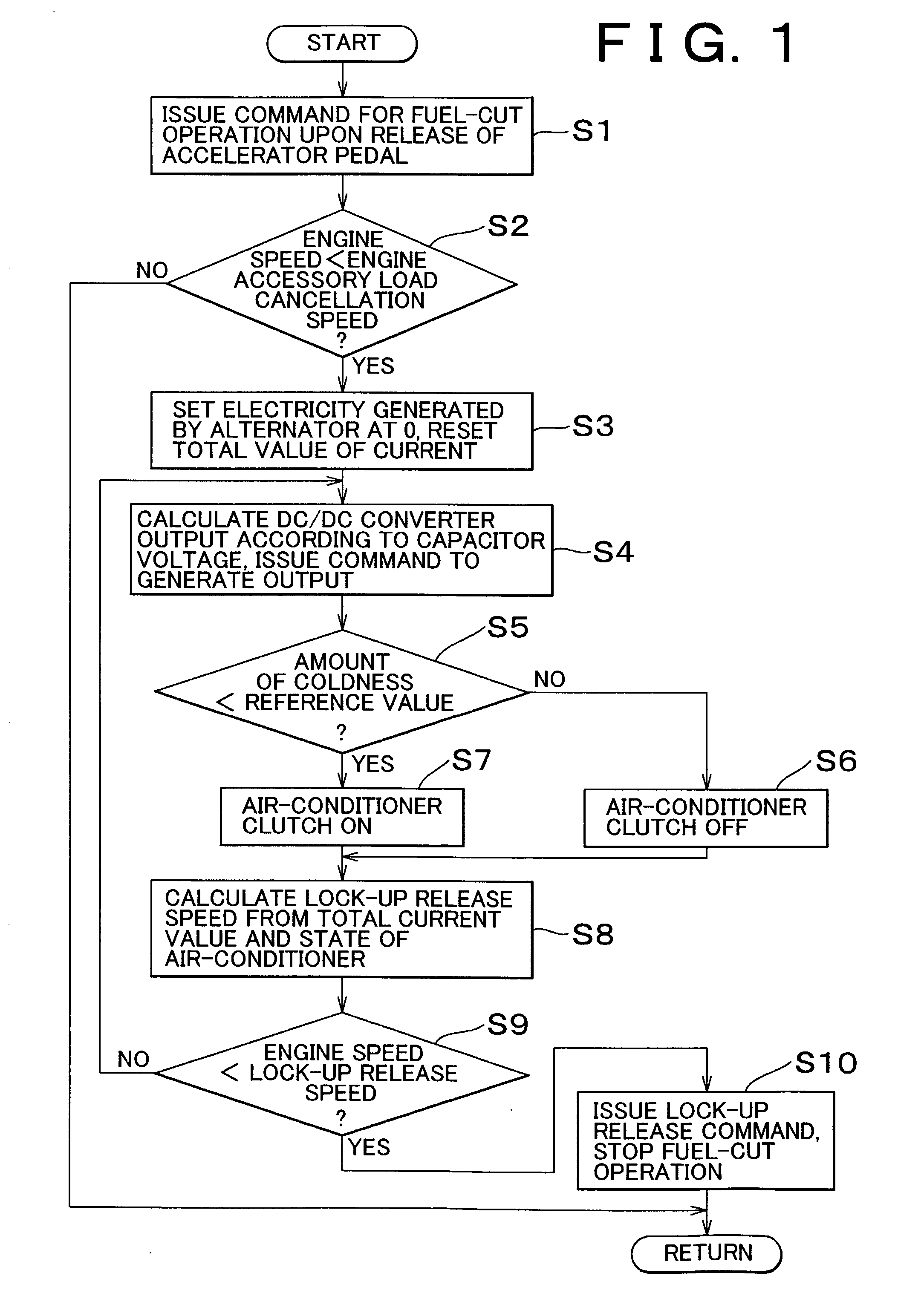
[0012] To achieve the above and / or other objects, the control apparatus and method according to one aspect of the invention reduces loads resulting from functional devices such as accessories operated by power transmitted from an internal combustion engine when a vehicle slows down with the internal combustion engine mechanically coupled on its output side to a drive train by means of a clutch so as to reduce a load applied to the internal combustion engine. The internal combustion engine typically is connected via a mechanical clutch to a drive train including a transmission. The vehicle includes one or more functional device(s) operated by a torque generated by the internal combustion engine. The control apparatus and method controls a load applied by the functional device on the internal combustion engine when the mechanical clutch is in an engaged state during deceleration of the vehicle and a speed of the internal combustion engine is lower than a predetermined value such that the load is reduced to a first value lower than a second value of the load applied to the engine when the speed of the internal combustion engine is equal to or higher than the predetermined value.
[0013] According to the aforementioned aspect, the mechanical clutch directly couples the internal combustion engine and the drive train with each other when the vehicle slows down, and the internal combustion engine drives the functional devices while this state is maintained. If the speed of the internal combustion engine gradually falls during slowdown of the vehicle and then becomes equal to or lower than a predetermined speed, loads applied to the internal combustion engine by the functional devices are made lower than the load applied before. The load applied to the internal combustion engine is reduced, and oscillation generated in the internal combustion engine is suppressed. Even if the mechanical clutch remains engaged, factors causing deterioration in driving comfort such as booming noise hardly arise. Thus, the mechanical clutch can be left engaged until the speed of the internal combustion engine reaches a relatively low speed. In other words, the period in which the mechanical clutch is engaged to maintain the speed of the internal combustion engine at or above a speed corresponding to resumption of the supply of fuel can be extended. Accordingly, it becomes possible to achieve improvement in fuel consumption.
[0014] According to another aspect of the invention, a function compensating device can be provided to compensate for a functional deterioration caused by reduction of the load of the functional device on the internal combustion engine.
[0015] According to the aforementioned aspect, if the load(s) applied to the internal combustion engine by the functional device(s) is / are reduced, namely, if the operational state(s) of the functional device(s) deteriorate, the function compensating device compensates for a loss in the functions of the functional devices. Therefore, the vehicle can be maintained in the same operational or running state as before.

Problems solved by technology

Low-frequency oscillation is sensed as a booming noise or the like and thus constitutes a factor causing deterioration in driving comfort.
Therefore, the internal combustion engine oscillates more violently, and oscillation or booming noise resulting therefrom tends to cause deterioration in driving comfort.
That is, if the internal combustion engine drives the accessories, oscillation of the internal combustion engine tends to occur due to an increased load.
In other words, a disadvantage arises in improving fuel consumption.
There is no technology that attempts to tackle this problem.

Method used


Image

  • Control apparatus and method for vehicle equipped with internal combustion engine
  • Control apparatus and method for vehicle equipped with internal combustion engine
  • Control apparatus and method for vehicle equipped with internal combustion engine

Examples


Embodiment Construction

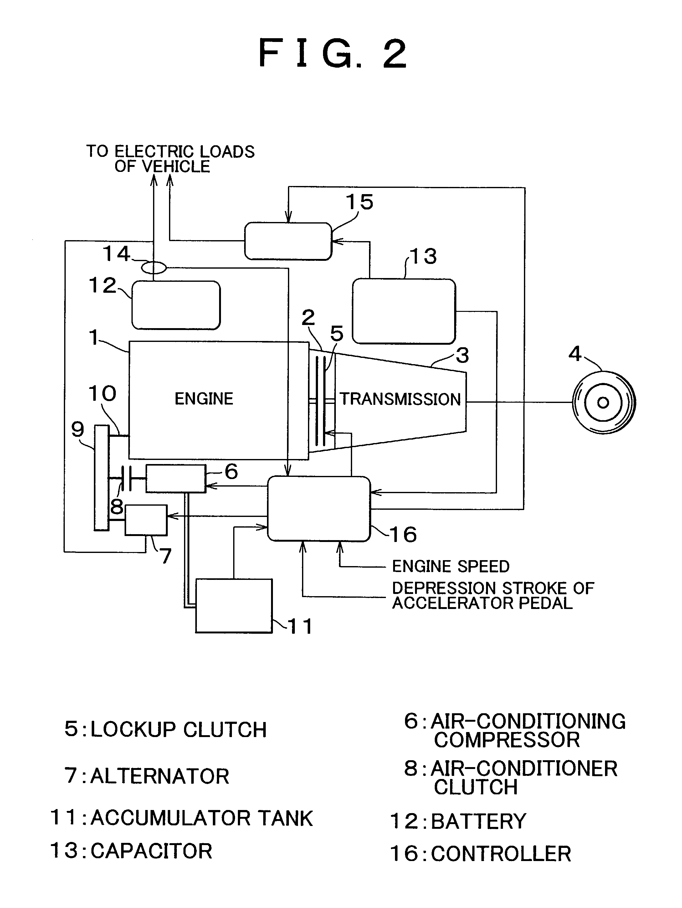
[0021] The invention will now be described with reference to an exemplary embodiment. First of all, an exemplary vehicle equipped with a control apparatus according to the invention will be described briefly. Referring to FIG. 2, a transmission 3 is connected to output side of an internal combustion engine (engine) 1 via a torque converter 2. The engine 1 functions as a power source. A torque output from the transmission 3 is transmitted to a driving wheel 4, whereby it becomes possible to drive the vehicle. A torque transmission system extending from the torque converter 2 to the driving wheel 4 constitutes a drive train.

[0022] The engine 1 is a power unit in which fuel is burnt to output power, and can be, for example, a gasoline engine or a diesel engine. The engine 1 is designed to be capable of electronically controlling throttle opening, fuel injection amount, ignition timing, or the like. For example, while the vehicle runs with a throttle fully closed, the supply of fuel is ...


PUM


Abstract

A vehicle includes an internal combustion engine that is variably connected, for example, via a mechanical clutch, to a drive train including a transmission. The vehicle also has a functional device operated by a torque generated by the internal combustion engine. A load applied by the functional device on the internal combustion engine when the drive train and the engine are engaged during deceleration of the vehicle and a speed of the internal combustion engine is lower than a predetermined value is controlled such that the load is reduced to a first value lower than a second value of the load applied to the engine when the speed of the internal combustion engine is equal to or higher than the predetermined value.

Description

INCORPORATION BY REFERENCE[0001] The disclosure of Japanese Patent Application No. 2001-239842 filed on Aug. 7, 2001, including the specification, drawings and abstract is incorporated herein by reference in its entirety.[0002] 1. Field of Invention[0003] The invention relates to a control apparatus and method for a vehicle which has an internal combustion engine such as, for example, a gasoline engine or a diesel engine connected on its output side via a mechanical clutch to a drive train including a transmission and which is equipped with functional devices such as accessories operating on the basis of a torque transmitted from the internal combustion engine.[0004] 2. Description of Related Art[0005] As is well known, there have been earnest demands for an improvement of fuel consumption in vehicles. To improve fuel consumption in a vehicle employing an internal combustion engine as a power source, it is desirable that the internal combustion engine be always operated with high ef...

Claims


Application Information

Patent Timeline
Patent Type & Authority Applications(United States)
IPC IPC(8): F16H61/14B60H1/32B60K6/12B60W10/30F02D41/08F02D41/12
CPCB60H1/3222B60K6/12B60L2240/441B60W2510/0208B60W2510/0638F02D41/022F02D41/083F02D41/123F02D2041/2058F02D2200/602F02D2250/24F16H61/143Y02T10/6208Y02T10/62
Inventor KAWAI, TAKASHITSUJII, HIROSHIKURETAKE, KENSUGIURA, MASANORIHANADA, HIDETO
Owner TOYOTA JIDOSHA KK
Learn More