Method for avoidance of an obstacle or an optical phenomenon which distorts quality of image
a technology of optical phenomenon and avoidance method, which is applied in the field of avoidance method of obstacle or optical phenomenon which distorts image quality, can solve the problems of unsuitable high-quality-oriented imaging methods, maintenance mechanisms, and the inability to reduce obstacles in number, so as to achieve high image quality and reduce image quality
- Summary
- Abstract
- Description
- Claims
- Application Information
AI Technical Summary
Benefits of technology
Problems solved by technology
Method used
Image
Examples
example 1
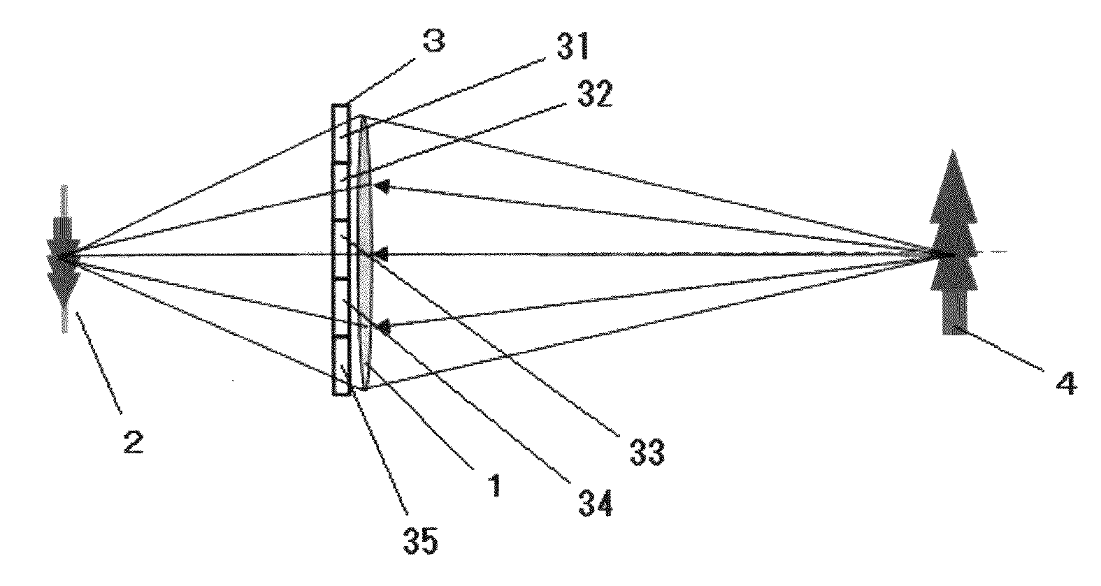
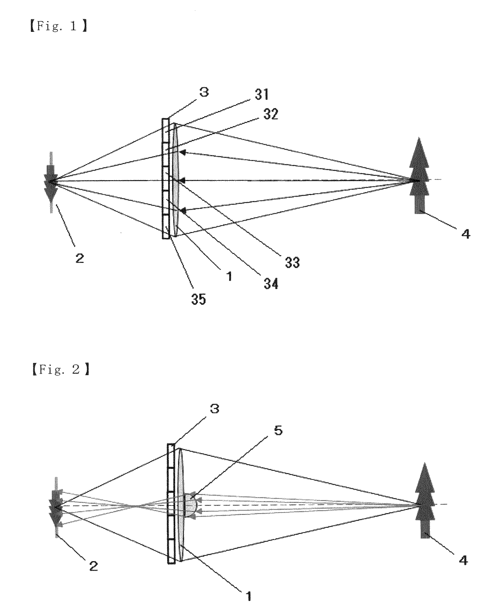
[0099]A device having a configuration shown in FIG. 12 was fabricated. That is, a lens 1 (“Canon EF lens 50 mm F1.8 II” manufactured by Canon Inc.) was first prepared. An image sensor 2 (“Canon EOS Kiss Digital X” manufactured by Canon Inc.) was disposed at the focal point of the lens. Five optical shutters were combined into a 2-mm-thick optical shutter array 3, which was then inserted as shown in FIG. 12. A protective cover 8 formed of a 2-mm-thick acrylic plate was disposed in the vicinity of the outer surface of the optical shutter array 3.
[0100]Water was then attached to the central portion of the protective cover 8 to form a water drop having a diameter of approximately 3 mm. The five optical shutters (optical shutters 31 to 35) were then sequentially opened to image a subject. FIGS. 13-1 to 13-5 show the results obtained by capturing images by sequentially opening the optical shutters 31 to 35. As shown in FIGS. 13-1 to 13-5, it has been ascertained that only the image captur...
example 2
[0103]Images were captured in a manner similar to Example 1 except that the following method was used as the method for detecting an obstacle in Example 1.
(Obstacle Detecting Method)
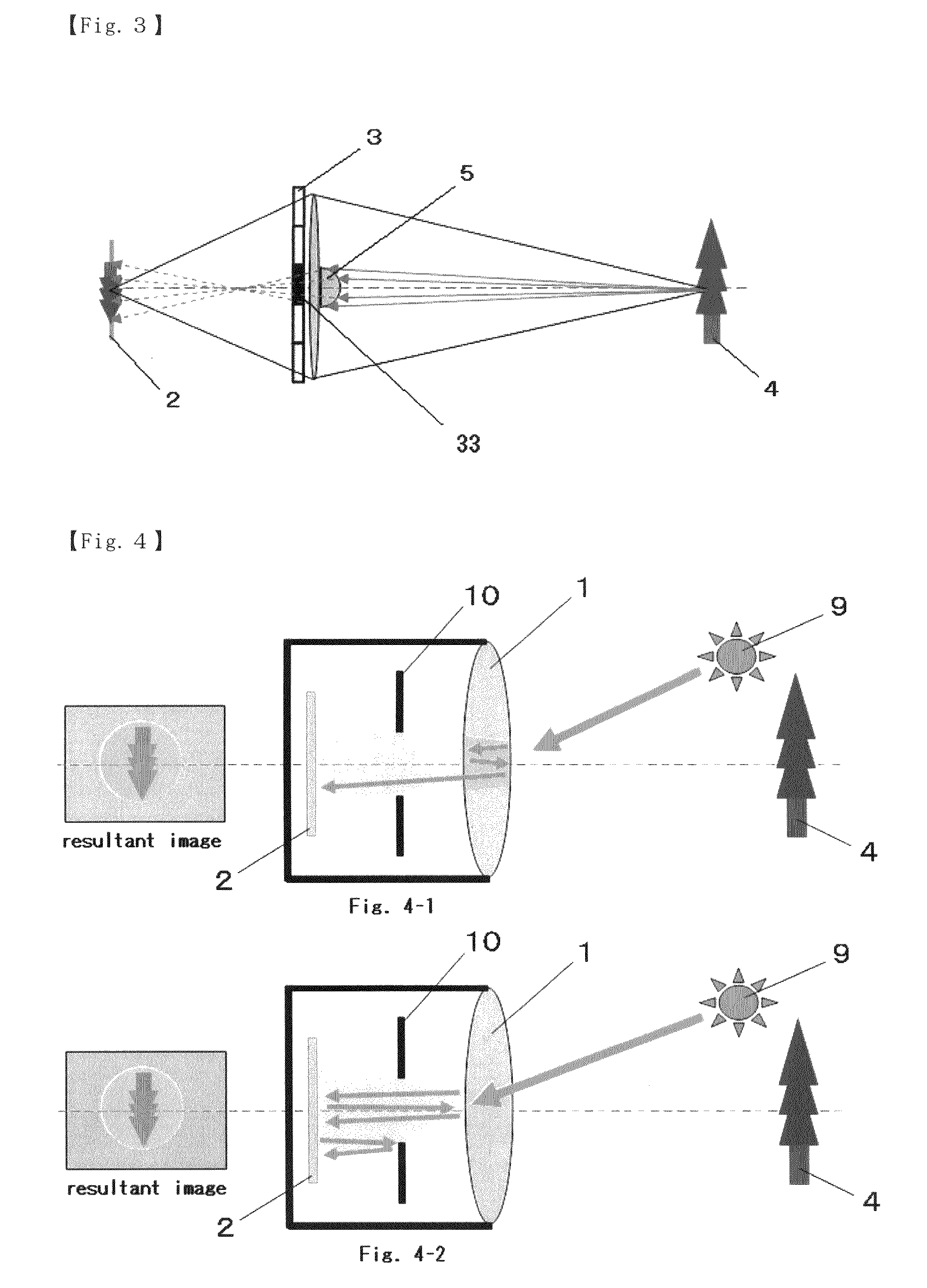
[0104]A red light source was used as the light source 6, and the light source 6 was disposed, as shown in FIG. 17, in such a way that the distance “x” from the light source 6 to the center of the protective cover 8 was 6 cm and the line connecting the center of the protective cover 8 to the center of the image sensor 2 and the line connecting the center of the protective cover 8 to the light source form an angle θ of 30 degrees. FIGS. 18-1 and 18-2 show the results obtained by imaging reflected light of irradiated light using the image sensor 2 (“Canon EOS Kiss Digital X” manufactured by Canon Inc.). FIG. 18-1 shows an image captured with no obstacle provided, and FIG. 18-2 shows an image captured with an obstacle (water drop) attached. As shown in FIGS. 18-1 and 18-2, the obstacle emerged in red when ir...
example 3
[0105]Images were captured in a manner similar to Example 1 except that imaging was conducted under the condition that the imaging device was irradiated with intense light from two locations instead of having water attached to the central portion of the protective cover 8 in Example 1. FIGS. 19-1 and 19-2 show the results. FIG. 19-1 shows an image captured by opening all the five optical shutters, and FIG. 19-2 shows an image captured by closing, among the five optical shutters, two optical shutters through which light affected by the optical phenomenon passed. Comparing with FIG. 19-1 and FIG. 19-2 shows that although the brightness as a whole is lower because the amount of light is low, the influence of the image-quality-degrading optical phenomenon can be avoided.
[0106]According to the method of the present invention, in an image affected by an obstacle attached to a lens or a protective cover for the lens in an imaging device or an optical phenomenon produced by the lens or the ...
PUM
 Abstract
Description
Claims
Application Information
 - R&D
- Intellectual Property
- Life Sciences
- Materials
- Tech Scout
- Unparalleled Data Quality
- Higher Quality Content
- 60% Fewer Hallucinations
Browse by: Latest US Patents, China's latest patents, Technical Efficacy Thesaurus, Application Domain, Technology Topic, Popular Technical Reports.
© 2025 PatSnap. All rights reserved.Legal|Privacy policy|Modern Slavery Act Transparency Statement|Sitemap|About US| Contact US: help@patsnap.com


