Push-in socket assembly

Active Publication Date: 2009-10-15
BURTON TECH
View PDF36 Cites 26 Cited by
  • Summary
  • Abstract
  • Description
  • Claims
  • Application Information

AI Technical Summary

Benefits of technology

[0008]The present invention provides a push-in socket that is cost-effective, easy to assemble, easily installed in a headla

Problems solved by technology

Several problems exist with installation of conventional sockets.
This requires extra time and cost in both manufacturing and installation.
Conventional snap-in sockets also have a disadvantage in that a through hole is required for the snap fit fingers to work.
Snap fit designs do not work in blind holes since a ledge inside the hole is needed for the snap

Method used


Image

  • Push-in socket assembly
  • Push-in socket assembly
  • Push-in socket assembly

Examples


Example

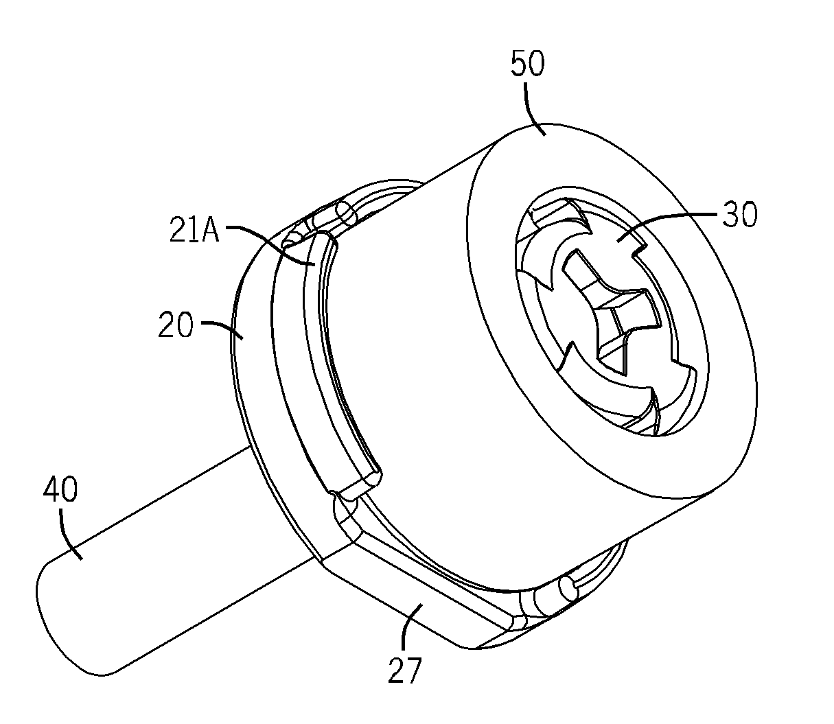
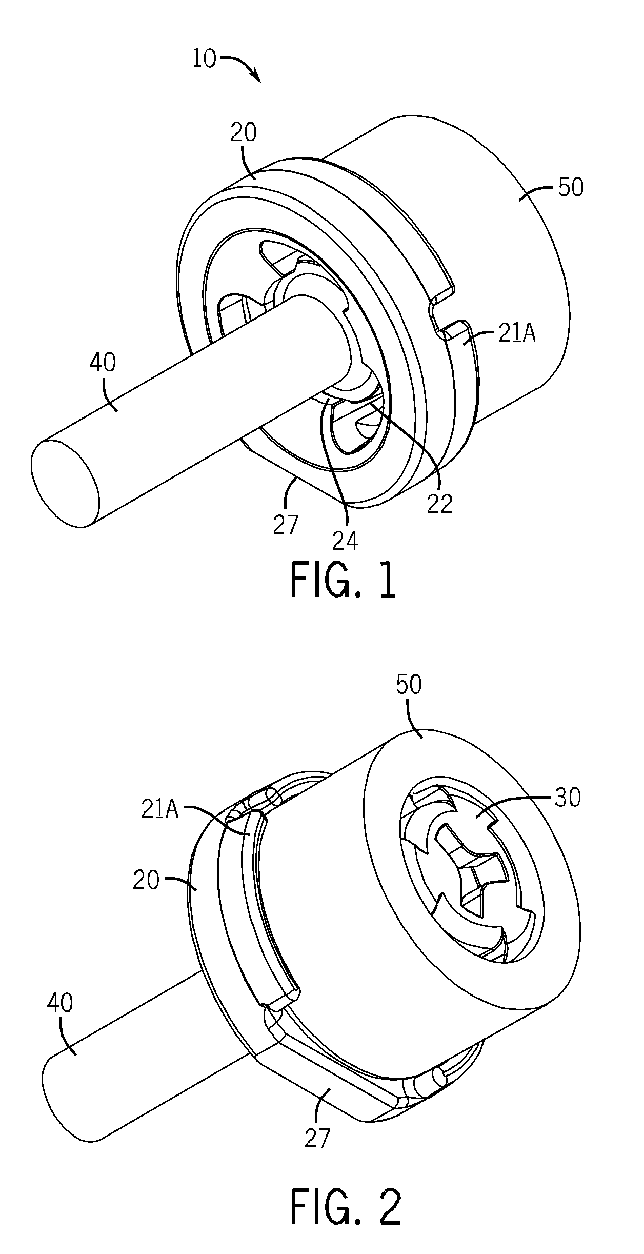
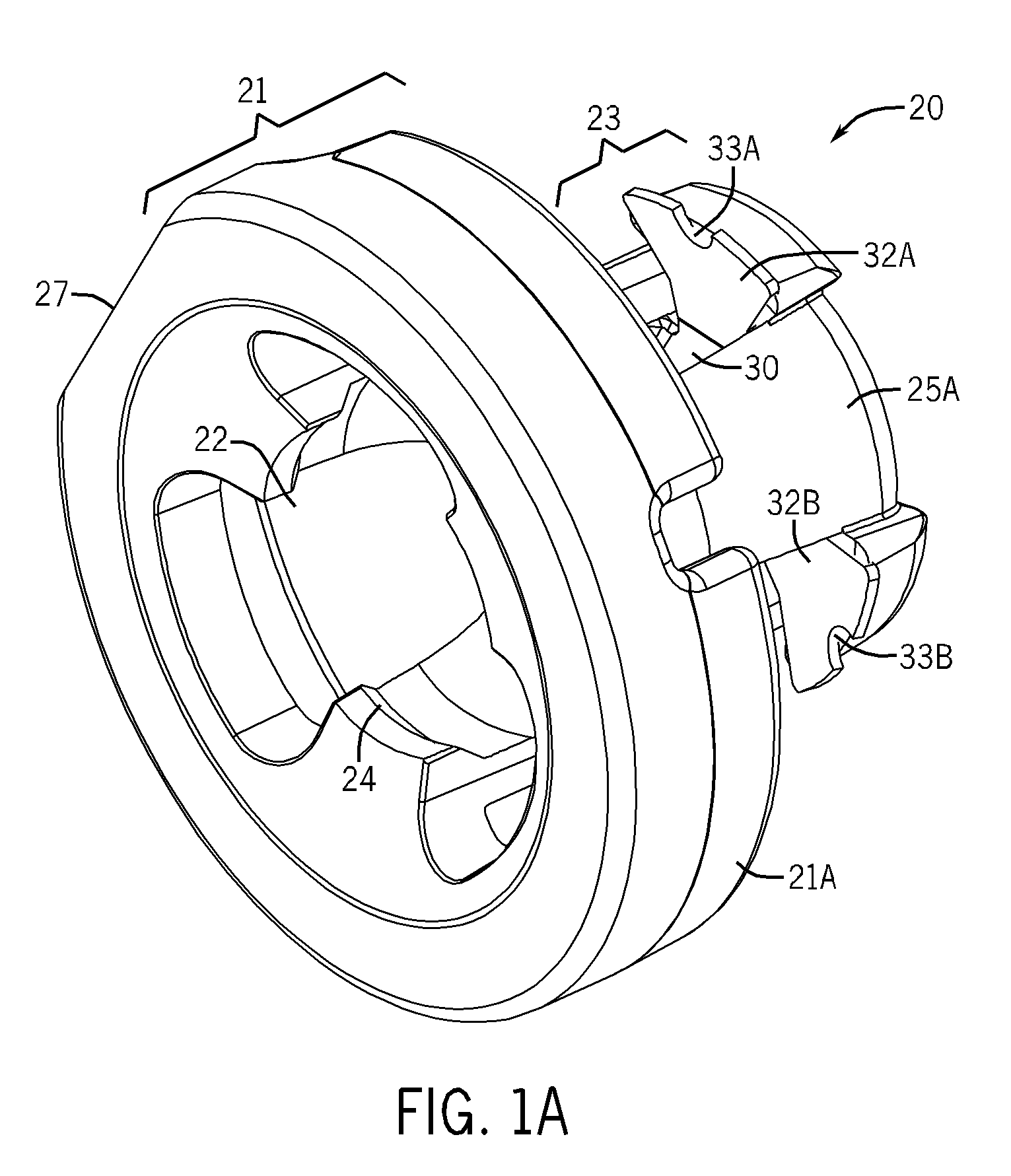
[0030]Certain embodiments of a push-in socket assembly 10 in accordance with the present invention as shown in the FIGURES. While the invention may be susceptible to embodiment in different forms, there is shown in the drawings, and herein will be described in detail, certain illustrative embodiments with the understanding that the present disclosure is to be considered an exemplification of the principles of the invention, and is not intended to limit the invention to those as illustrated and described herein. Additionally, features illustrated and described with respect to one embodiment could be used in connection with other embodiments.

[0031]An improved push-in socket assembly 10 is shown in FIGS. 1-3. The assembly 10 consists of a socket 20 and a retainer clip 30. Socket assembly 10 can be used with conventional ball studs of various shapes or disengageable ball studs. In the embodiment shown in the figures, a semi-spherical ball stud 40 with a lip 44 on the head 42 of the ball...


PUM


Abstract

A ball socket for connection with a ball stud provides for easy manufacturing and assembly using a flat-stamped flexible retainer clip. The retainer clip is inserted into the socket and flexes to snap-fit within in the socket. The flex of the clip also flexes wings of the clip which engage with a receiving boss or socket. The flexion of the clip allows for easy push-in of the socket and sufficient resistance to accidental pull-out. The push-in socket design eliminates the need for screw-mounting of the socket. The socket assembly may be manufactured for use in connection with disengageable or conventional ball studs.

Description

BACKGROUND OF THE INVENTION[0001]This invention relates generally to pivot joints, and in particular to a pivot joint useful for connecting a headlamp adjustor to a reflector inside a headlamp assembly or an external reflector and lens headlamp assembly. The improved socket assembly can be used effectively with many types of ball studs, including disengageable ball studs or conventional spherical, semi-spherical or “eared” ball studs.[0002]Pivotable spherical joints, commonly referred to as ball joints, include a ball stud engaged in a socket. Such joints have a wide variety of applications where a pivotable connection between two parts is desirable. For example, they may be used in many types of linear actuators and have been found to be particularly useful in automotive lamp assemblies. As seen in U.S. Pat. No. 5,707,133, automotive lamp assemblies used as headlights typically comprise several basic parts: a support frame, a reflector, a lens, a bulb, and one or more adjusters.[00...

Claims


Application Information

Patent Timeline
IPC IPC(8): B60Q1/068F16C11/06F21V21/14
CPCB60Q2200/32F16C11/069F21S48/1317Y10T29/49826F16C11/0657Y10T403/32631F16C2326/01
Inventor BURTON, JOHN
Owner BURTON TECH
Why Eureka
Try Eureka