Waveguide with asymmetric outcoupling

a waveguide and asymmetric technology, applied in the field of waveguides, can solve problems such as insufficient spatial uniformity, and achieve the effect of improving the spatial uniformity of ligh

Inactive Publication Date: 2009-10-15
KONINKLIJKE PHILIPS ELECTRONICS NV
View PDF12 Cites 8 Cited by
  • Summary
  • Abstract
  • Description
  • Claims
  • Application Information

AI Technical Summary

Benefits of technology

[0009]In view of the above-mentioned and other drawbacks of the prior art, an object of the present invention is to provide a more energy-efficient way of improving spatial uniformity of light emitted by a waveguide.

Problems solved by technology

Also in the case of white or colored light emitted by a single light source and guided through a waveguide, insufficient spatial uniformity may be experienced, especially at some distance away from the extraction edge(s) of the waveguide.

Method used


Image

  • Waveguide with asymmetric outcoupling
  • Waveguide with asymmetric outcoupling
  • Waveguide with asymmetric outcoupling

Examples


Embodiment Construction

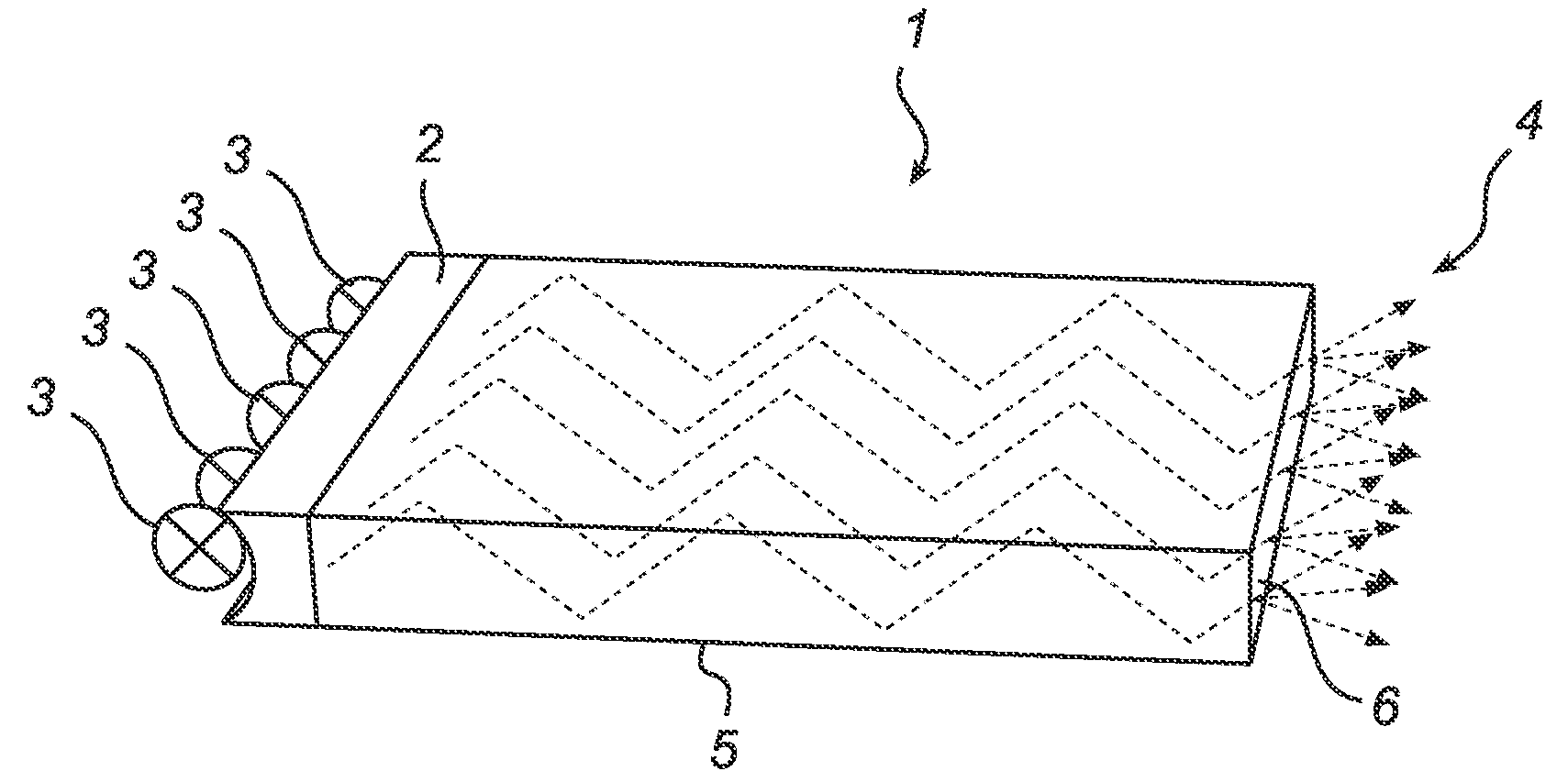
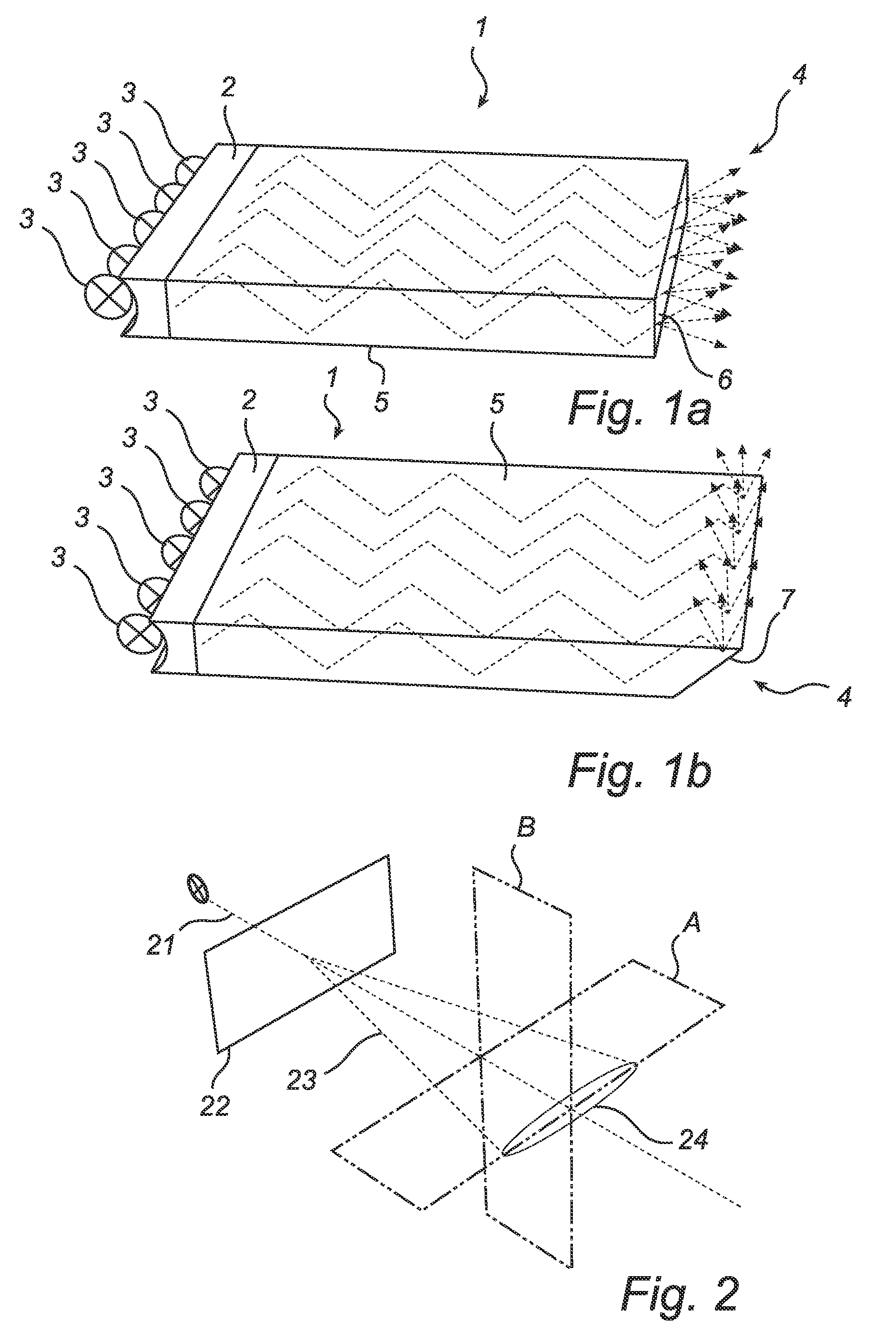
[0027]FIGS. 1a-b show a flat planar waveguide 1 comprising an incoupling structure 2 adapted to receive light from a plurality of light sources 3, e.g. LEDs, and an outcoupling structure 4, adapted to couple light out of the waveguide 1. Between the incoupling structure 2 and the outcoupling structure 4, light is retained in the waveguide 1 by guiding edges 5. The guiding edges 5 may rely upon total internal reflection (TIR), reflectors, or a combination of TIR and reflectors at the edges and / or top and / or bottom surfaces.

[0028]The waveguide can be formed of a slab of a single dielectric material or combinations of dielectric materials. Suitable dielectric materials include different transparent materials, such as various types of glass, poly-methyl methacrylate (PMMA) etc. The waveguide may also be air, at least partly enclosed by waveguide reflectors. The material of the waveguide is preferably selected such that the interface between the waveguide and the surrounding medium fulfi...


PUM


Abstract

A waveguide (1), arranged to guide light from at least one light source (3), comprising an outcoupling structure (4) adapted to enable outcoupling of said light from said waveguide in a general outcoupling direction, and at least one guiding edge (5) adapted to contain said light in said waveguide by reflecting said light on its way towards said outcoupling structure, wherein the outcoupling structure comprises an asymmetrically diffusing layer (6; 7). Such asymmetric diffusion improves the color mixing, and removes or limits the occurrence of color bands or intensity bands, while limiting the divergence in the direction where no color mixing or intensity variation problems exist.

Description

TECHNICAL FIELD[0001]The present invention relates to a waveguide, arranged to guide light from at least one light source, the waveguide comprising at least one guiding edge adapted to contain the light in the waveguide, and an extraction edge adapted to enable extraction of the light from the waveguide.[0002]The invention further relates to a lighting device comprising such a waveguide and a display device including such a lighting device.TECHNICAL BACKGROUND[0003]There are several lighting applications in which light from at least one light source is coupled into a waveguide and emitted from one or several surfaces of the waveguide. In some applications, for example a backlight for a liquid-crystal display, light can be coupled out through a top surface of a large size planar waveguide. In other applications, light can be coupled out at one or several edges of the waveguide. By using a planar waveguide and coupling light out at at least one of its edges, several different types of...

Claims


Application Information

Patent Timeline
Patent Type & Authority Applications(United States)
IPC IPC(8): G02B6/42
CPCG02B6/003G02B6/0045F21S8/06G02B6/0068G02B6/0055
Inventor VAN GORKOM, RAMON PASCALKRIJN, MARCELLLINUS PETRUS CAROLUS MICHAELBERGMAN, ANTHONIE HENDRIKVISSENBERG, MICHEL CORNELIUS JOSEPHUS MARIEIJZERMAN, WILLEM LUBERTUSHOOGENSTRAATEN, WILLEM FRANCISCUS JOHANNES
Owner KONINKLIJKE PHILIPS ELECTRONICS NV
Why Eureka
Try Eureka