Plasma processing apparatus and method

a processing apparatus and plasma technology, applied in the field of processing chambers, can solve the problems of parasitic plasma formation, increase in the possibility of premature gas breakdown prior to the gas passing through the showerhead, etc., and achieve the effect of reducing the formation of parasitic plasma in the gas tubes leading to the processing chamber

Inactive Publication Date: 2009-10-15
APPLIED MATERIALS INC
View PDF19 Cites 176 Cited by
  • Summary
  • Abstract
  • Description
  • Claims
  • Application Information

AI Technical Summary

Benefits of technology

[0007]The present invention generally includes a PECVD processing chamber having an RF power source coupled to the backing plate at a location separate from the gas source. By feeding the gas into the processing chamber at a location separate from the RF power, parasitic plasma formation in

Problems solved by technology

With the increase in RF current, the possibility of premature gas breakdown prior to the gas passing thr

Method used


Image

  • Plasma processing apparatus and method
  • Plasma processing apparatus and method
  • Plasma processing apparatus and method

Examples


Embodiment Construction

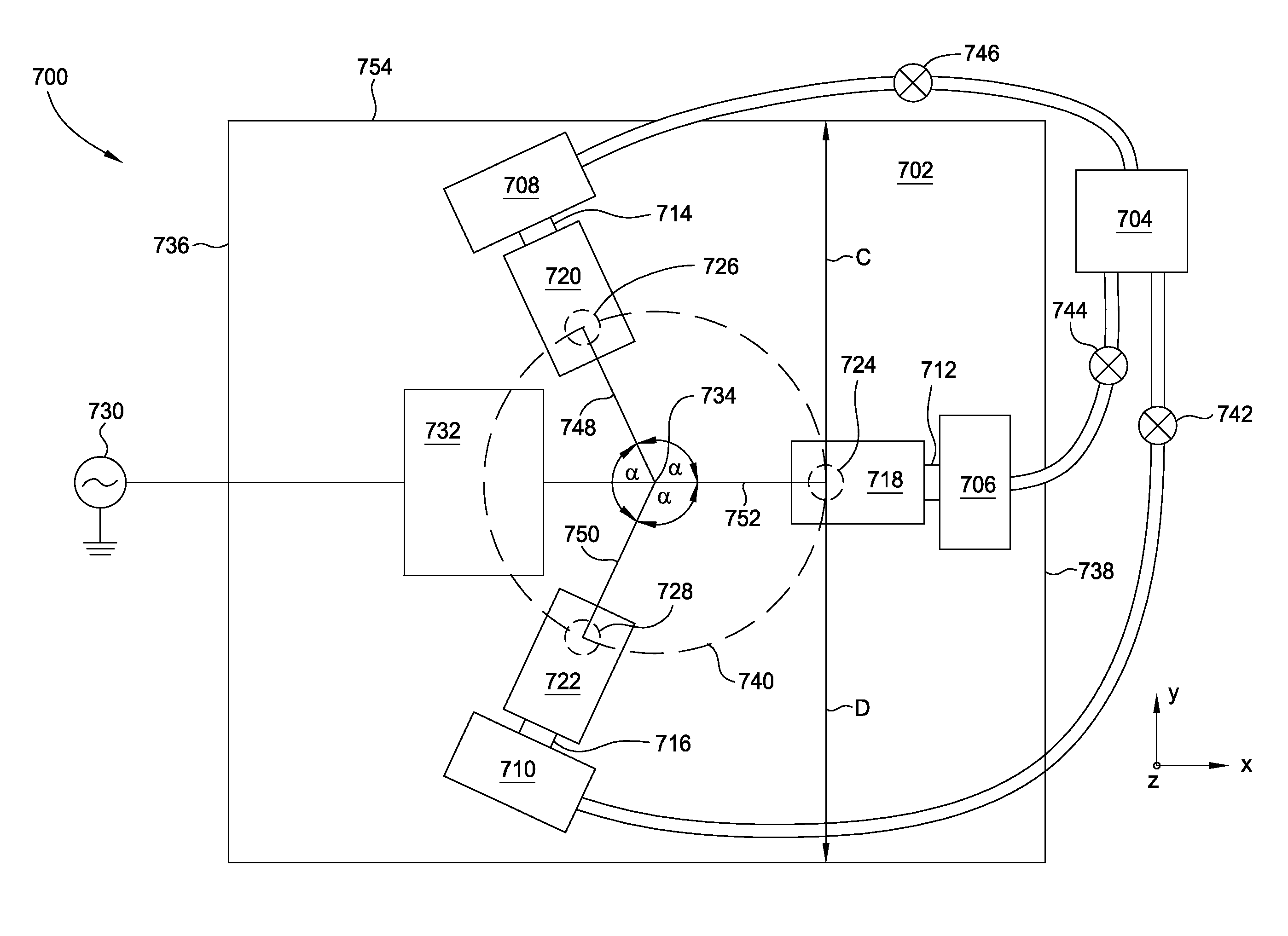
[0023]The present invention generally includes a PECVD processing chamber having an RF power source coupled to the backing plate at a location separate from the gas source. By feeding the gas into the processing chamber at a location separate from the RF power, parasitic plasma formation in the gas tubes leading to the processing chamber may be reduced. The gas may be fed to the chamber at a plurality of locations. At each location, the gas may be fed to the processing chamber from the gas source by passing through a remote plasma source as well as an RF choke or RF resistor.

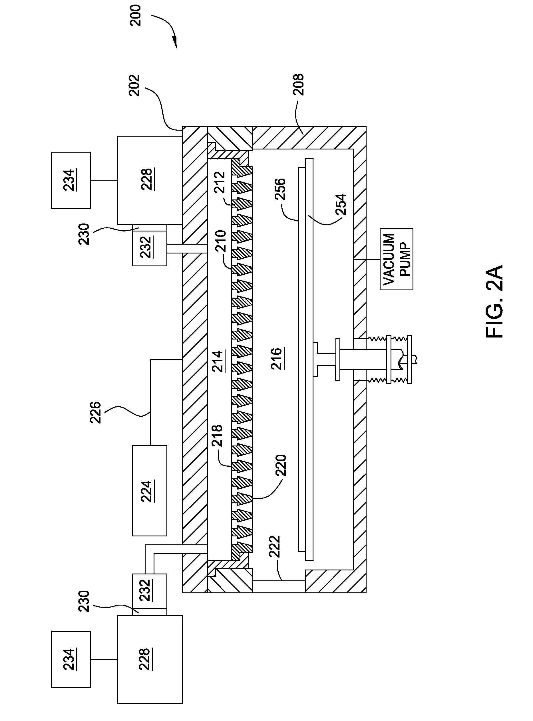
[0024]The invention is illustratively described below in reference to a chemical vapor deposition system, processing large area substrates, such as a PECVD system, available from AKT America, Inc., a division of Applied Materials, Inc., Santa Clara, Calif. However, it should be understood that the apparatus and method may have utility in other system configurations, including those systems configured to process ...


PUM

PropertyMeasurementUnit
Angleaaaaaaaaaa
Timeaaaaaaaaaa
Timeaaaaaaaaaa

Abstract

The present invention generally includes a plasma enhanced chemical vapor deposition (PECVD) processing chamber having an RF power source coupled to the backing plate at a location separate from the gas source. By feeding the gas into the processing chamber at a location separate from the RF power, parasitic plasma formation in the gas tubes leading to the processing chamber may be reduced. The gas may be fed to the chamber at a plurality of locations. At each location, the gas may be fed to the processing chamber from the gas source by passing through a remote plasma source as well as an RF choke or RF resistor.

Description

CROSS-REFERENCE TO RELATED APPLICATIONS[0001]This application is a continuation-in-part of U.S. patent application Ser. No. 12 / 271,616 (APPM / 13370), filed Nov. 14, 2008, which is herein incorporated by reference, which application claims priority to U.S. Provisional Patent Application Ser. No. 61 / 044,481 (APPM / 013370L), filed Apr. 12, 2008, both of which are herein incorporated by reference. This application also claims priority to U.S. Provisional Patent Application Ser. No. 61 / 139,384 (APPM / 13370L02) filed Dec. 19, 2008 and U.S. Provisional Patent Application Ser. No. 61 / 044,481 (APPM / 013370L), filed Apr. 12, 2008, both of which are herein incorporated by reference.BACKGROUND OF THE INVENTION[0002]1. Field of the Invention[0003]Embodiments of the present invention generally relate to a processing chamber having the power supply coupled to the processing chamber at a location separate from the gas supply.[0004]2. Description of the Related Art[0005]As demand for larger flat panel d...

Claims


Application Information

Patent Timeline
IPC IPC(8): C23C16/44C23C16/00H05H1/24
CPCC23C16/4405C23C16/507H01J2237/3321H01J37/3244H01J37/32357
Inventor FURUTA, GAKUCHOI, YOUNG-JINCHOI, SOO YOUNGPARK, BEOM SOOWHITE, JOHN M.ANWAR, SUHAILTINER, ROBIN L.
Owner APPLIED MATERIALS INC
Why Eureka
Try Eureka