
Capillary Action Collection Device and Container Assembly

a collection device and a technology for container assembly, applied in medical science, laboratory glassware, vaccination/ovulation diagnostics, etc., can solve the problems of significant dead volume amount of sample trapped within the collection cavity, the collection cavity of conventional collection containers is typically straight-walled, and does not provide specimen flow-enhancing features

Active Publication Date: 2009-10-15
BECTON DICKINSON & CO
View PDF37 Cites 84 Cited by
  • Summary
  • Abstract
  • Description
  • Claims
  • Application Information

AI Technical Summary

Benefits of technology

[0020]In one configuration, the wall element has an element height, and travels less distance than the element height when moving from the first position to the second position. The wall element may be frictionally engaged with the collection container in both the first position and the second position, such that a frictional force exists betw

Problems solved by technology

The internal collection cavities of conventional collection containers are typically straight-walled and do not provide any specimen flow-enhancing features.
Conventional containers typically do not promote the flow of drawn blood into the cavity during the collection process, and a typically not structured to allow direct withdrawal of a sample from within the cavity by standard instrumentation.
Accordingly, a significant amount of the collected blood or specimen sample is trapped on the sidewall of the cavity due to surface tension during collection and during transfer.
As a result, a significant dead volume amount of sample is trapped within the collection cavity during transfer of the specimen, since neither the collection container nor the cap assembly adequately funnel or channel the collected blood sample to the aspiration hole of the probe needle.

Method used


Image

  • Capillary Action Collection Device and Container Assembly
  • Capillary Action Collection Device and Container Assembly
  • Capillary Action Collection Device and Container Assembly

Examples


Embodiment Construction

[0049]For purposes of the description hereinafter, spatial orientation terms, if used, shall relate to the referenced embodiment, device, component, or feature as it is oriented in the accompanying drawing figures or otherwise described in the following detailed description. However, it is to be understood that the embodiments, devices, components, or features described herein may assume many alternative variations. It is also to be understood that the specific embodiments, devices, components, and features illustrated in the accompanying drawing figures and described herein are simply exemplary and should not be considered as limiting.

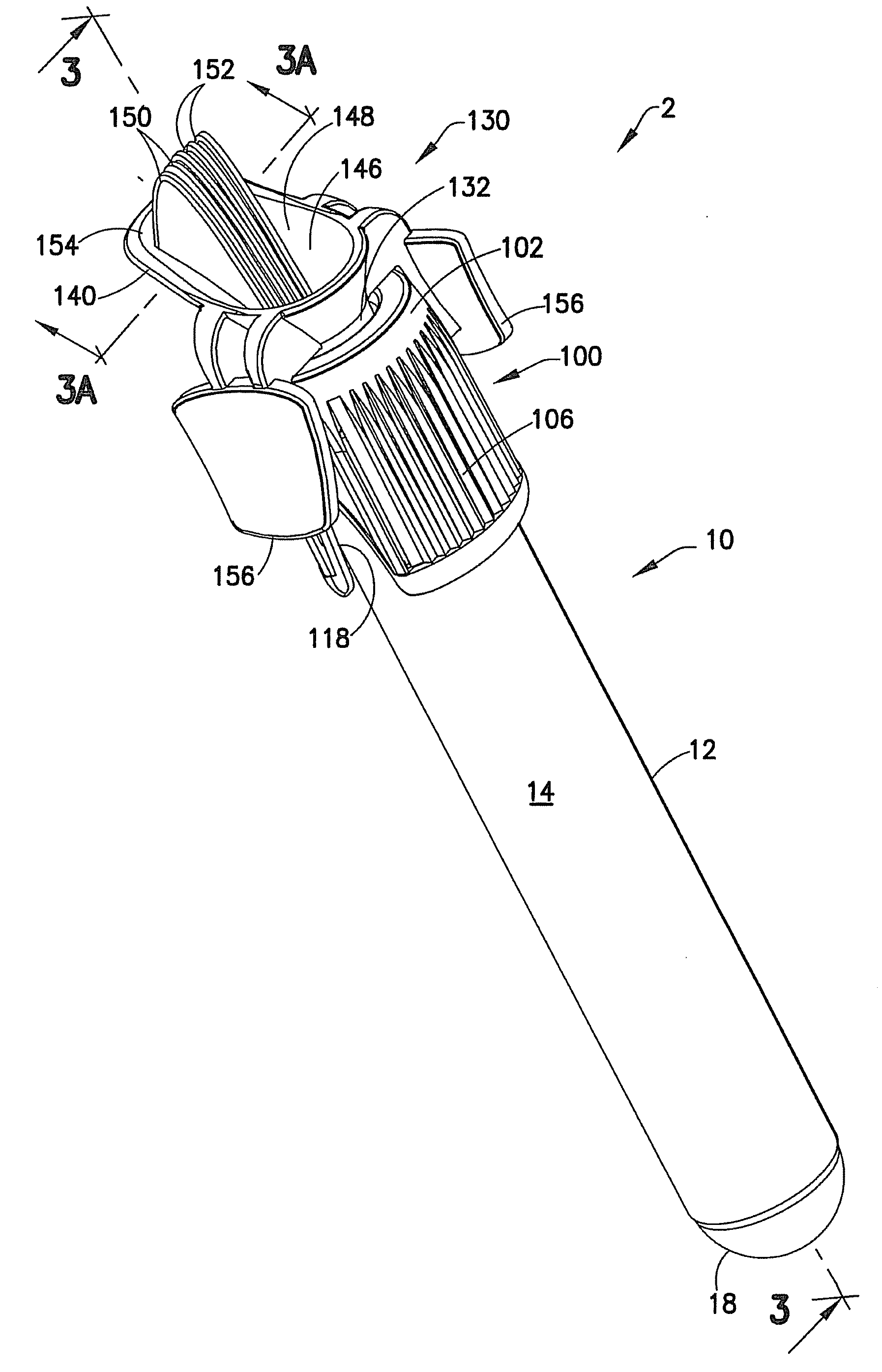
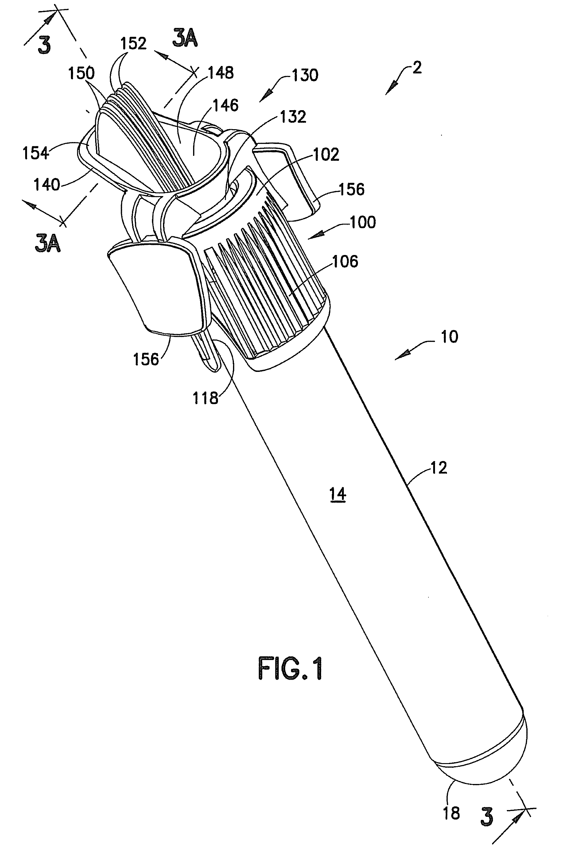
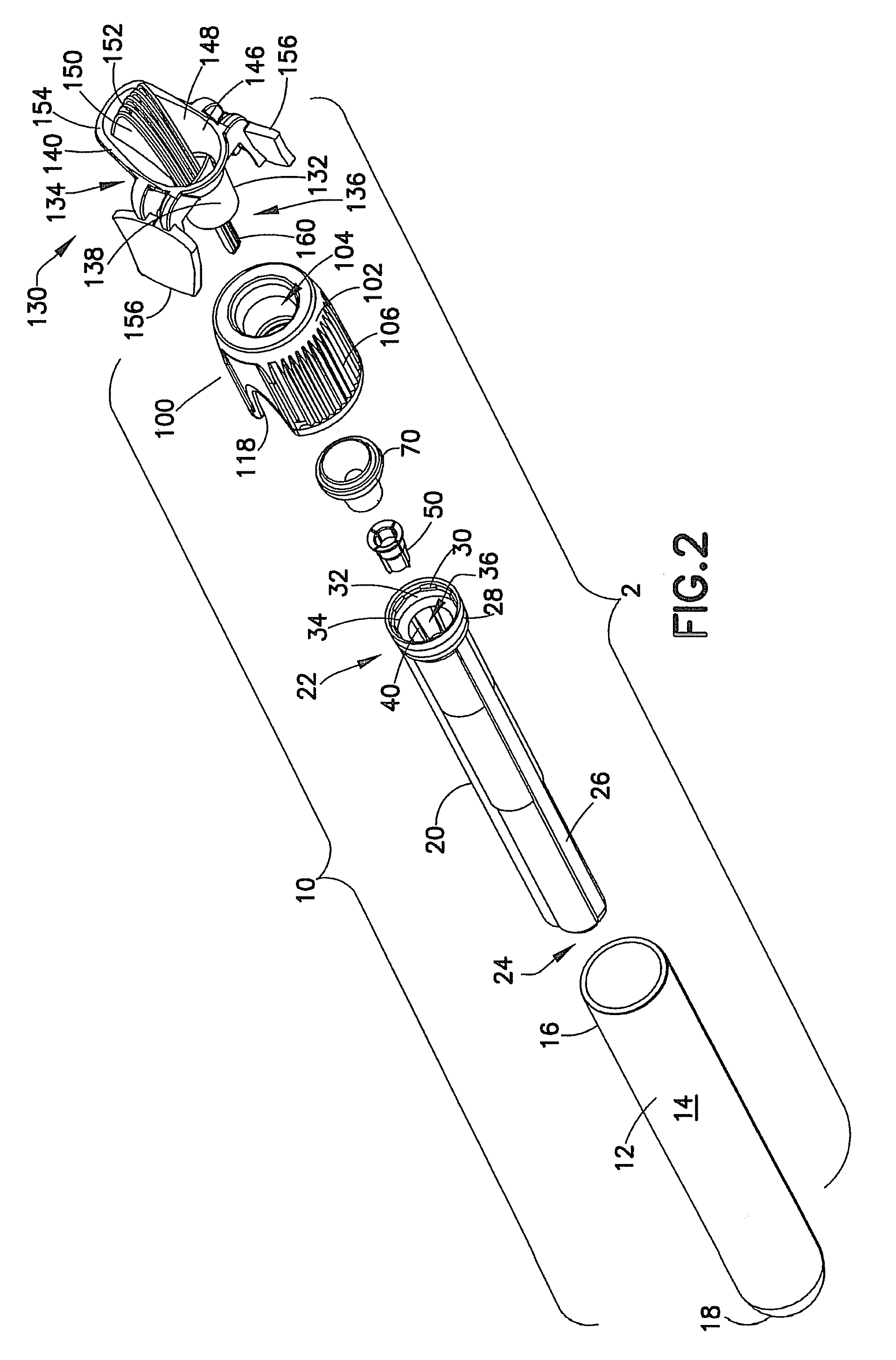
[0050]Referring initially to FIGS. 1-4, a device 2 for collecting a fluid sample, such as a blood sample, is generally shown. Collection device 2 is an assembly of components, generally comprising a container assembly 10 and a collector 130 adapted to access the container assembly 10 and, further, guide fluid flow under capillary action into container...


PUM


Abstract

A container assembly is disclosed including an outer container, a hollow inner member, and a closure. The outer container has a closed bottom, an open top, and a sidewall extending therebetween. The hollow inner member is disposed within the outer container and has an inner surface defining at least one capillary channel. The inner member includes a first end adjacent to the open top of the outer container and has an outer periphery seated against the sidewall of the outer container. The closure has a proximal end and a distal end. The closure proximal end is seated at least partially within the first end of the inner member to seal the outer container and inner member and define a fluid collection chamber. The closure distal end defines a recessed area shaped to direct fluid under capillary action to the at least one capillary channel in the inner member.

Description

CROSS REFERENCE TO RELATED APPLICATION[0001]This application claims priority to U.S. Provisional Patent Application No. 61 / 034,025, filed Mar. 5, 2008, entitled “Capillary Action Collection Device and Container Assembly”, the entire disclosure of which is herein incorporated by reference.BACKGROUND OF THE INVENTION[0002]1. Field of the Invention[0003]The present invention relates to a device for the collection, storage, and transfer of a blood or specimen sample obtained from a patient for medical diagnostic testing. More specifically, the present invention relates to a device for collection of blood samples from a patient. The device also includes a cap assembly having a stopper for closing and sealing the device after the blood or specimen sample has been collected. The stopper incorporates space elimination features to funnel the blood or specimen sample to a probe assembly of a testing instrument during transfer from the collection tube.[0004]2. Description of Related Art[0005]C...

Claims


Application Information

Patent Timeline
IPC IPC(8): A61B5/151
CPCA61B5/1405A61B10/0096B01L3/5021B01L2200/026B01L2300/042B01L2400/0409B01L2300/0609B01L2300/0672B01L2300/0838B01L2300/087B01L2300/047A61B5/150022A61B5/150259A61B5/150267A61B5/150351A61B5/150343A61B5/1438A61B5/154A61B5/150061A61B5/153
Inventor BARTFELD, BENJAMINWILKINSON, BRADLEY M.DASTANE, AJIT
Owner BECTON DICKINSON & CO
Learn More