Brake device of robot arm

a robot arm and brake device technology, applied in the field of robot arms, can solve the problems of increasing manufacturing cost and assembly difficulty, and achieve the effects of reducing the prepressing force of the prepressing plate, increasing the braking moment of the friction force, and increasing the friction for

Active Publication Date: 2016-05-05
TECHMAN ROBOT INC
View PDF13 Cites 7 Cited by
  • Summary
  • Abstract
  • Description
  • Claims
  • Application Information

AI Technical Summary

Benefits of technology

[0013]In summary, since the diameter of the brake disc is much larger than the diameter of the ratchet, a contacting area of the brake disc is increased to generate a greater friction force. Furthermore, the rotating torque of shaft is transferred to the brake disc having a larger diameter via the combining pin, the combining plate, and the plurality of guiding pins for extending the moment arm of the friction force, so as to increase the braking moment of the friction force. Additionally, a prepressing force of the prepressing plate can be reduced because the brake disc has a larger diameter, which prevents the parts from being worn out and extends service life of the parts. Besides, the present invention further can stop the shaft from rotating precisely.

Problems solved by technology

Therefore, it is required to replace materials and parts to endure higher stresses, which raises manufacturing cost and difficulty of assembly.

Method used


Image

  • Brake device of robot arm
  • Brake device of robot arm
  • Brake device of robot arm

Examples


Embodiment Construction

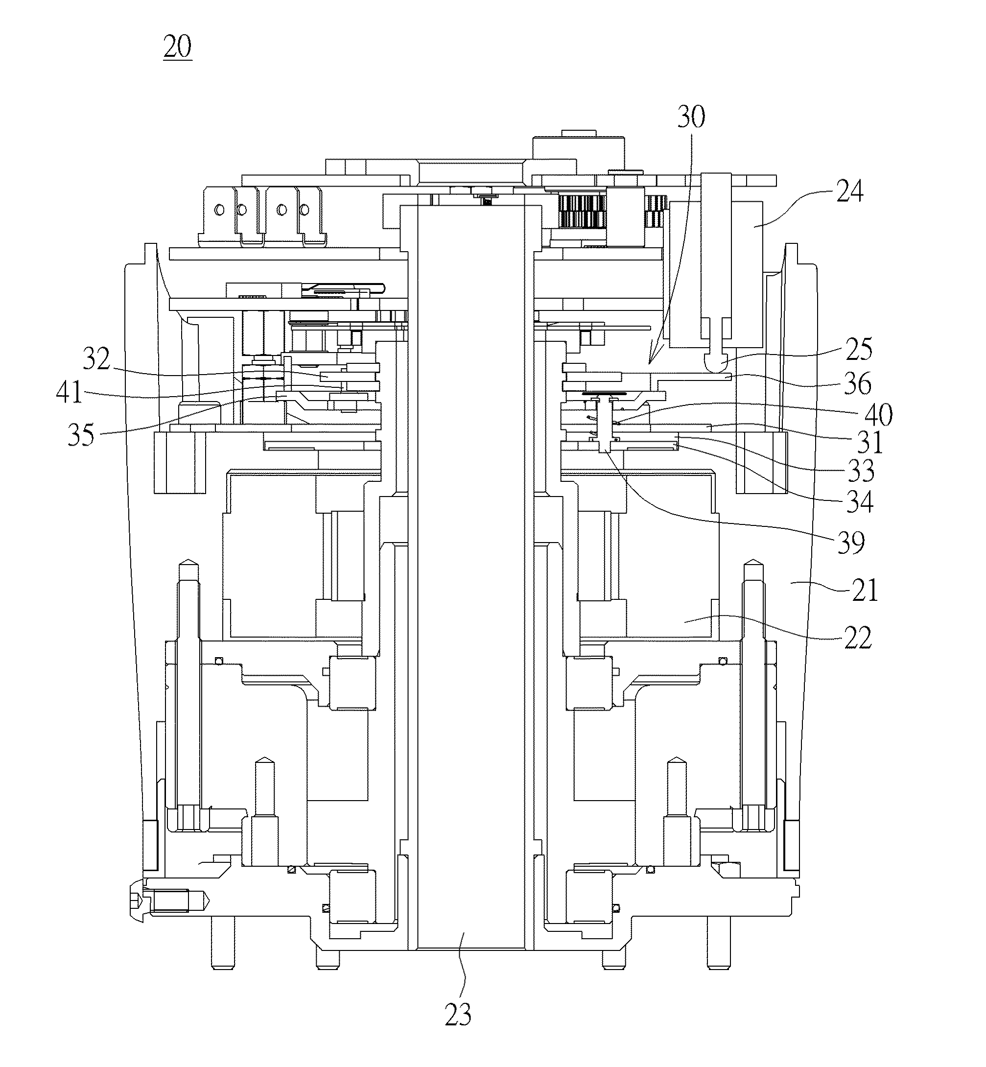
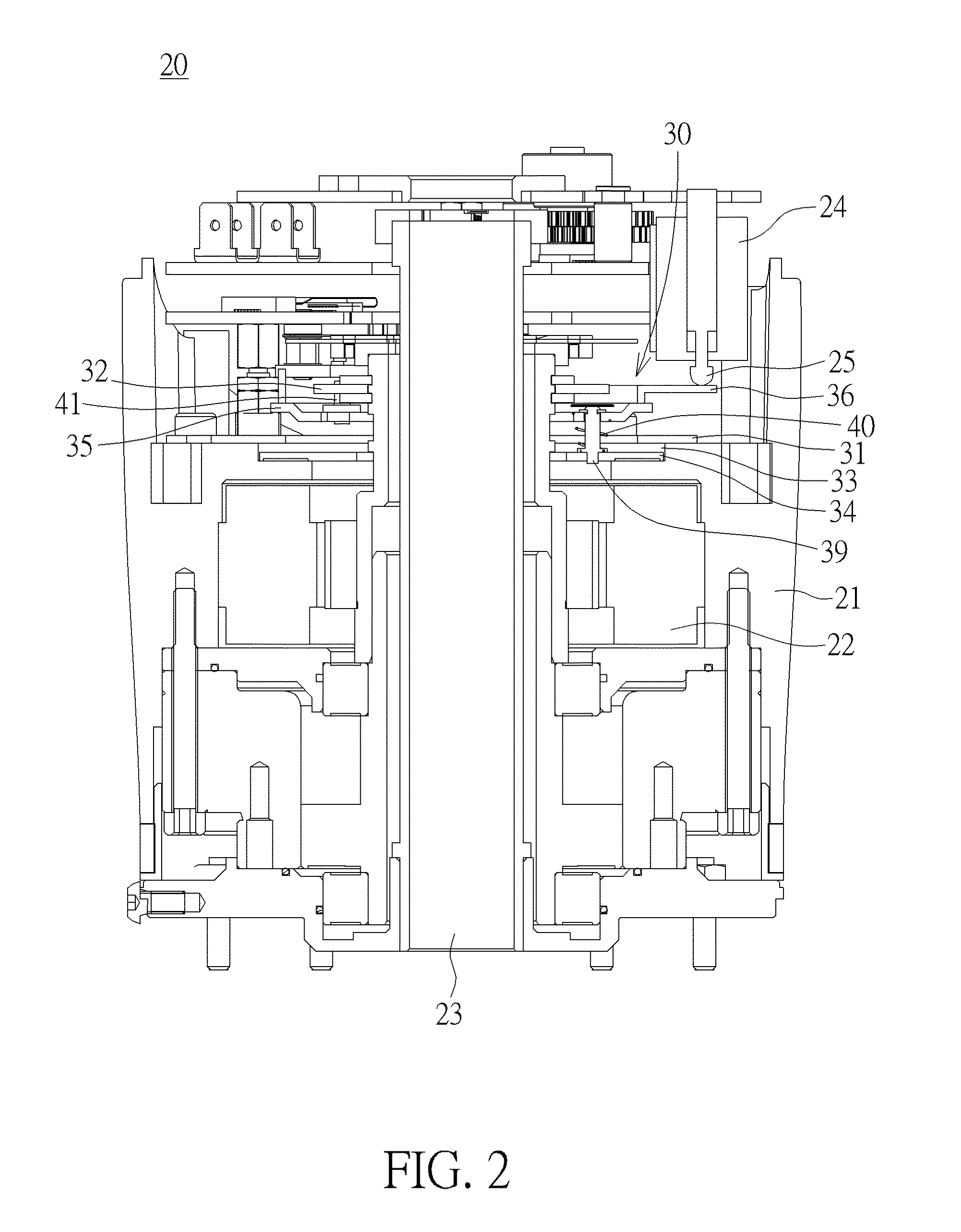
[0020]Please refer to FIG. 2 and FIG. 3. FIG. 2 is a lateral view of a driving module 20 of a robot arm at a braking position according to an embodiment of the present invention. FIG. 3 is a perspective diagram of a brake device 30 at the braking position according to the embodiment of the present invention. As shown in FIG. 2 and FIG. 3, the robot arm includes the driving module 20 and the brake device 20. The driving module 20 of the robot arm includes a housing 21, a motor 22, a shaft 23, a solenoid valve 24, and an operating rod 25. The motor 22 sheathes on the shaft 23 disposed at a center of the housing 21 and drives the shaft 23 to rotate for moving the robot arm. The solenoid valve 24 is fixed on the housing 21 for controlling the operating rod 25 to activate or release the brake device 30. The brake device 30 of the present invention is disposed inside the housing 21 of the driving module 20

[0021]The brake device 30 includes a prepressing plate 31, a ratchet 32, a brake res...


PUM


Abstract

A brake device of a robot arm utilizes a brake disc whose diameter is much larger than a diameter of a ratchet for increasing a contacting area of the brake disc, so as to generate a greater friction force. The brake device further utilizes a combining pin, a combining plate, and a plurality of guiding pins for transferring a rotating torque to the brake device having a larger diameter, so as to extend a moment arm of the friction force and generate a greater moment, which reduces a prepressing force and extends life of the brake device.

Description

BACKGROUND OF THE INVENTION[0001]1. Field of the Invention[0002]The present invention relates to a robot arm, and more particularly, to a brake device for stopping a motor of a robot arm from rotating as the robot arm is ceased.[0003]2. Description of the Prior Art[0004]A robot arm capable of taking a work piece and moving back and forth is usually applied to an automated factory for increasing a manufacturing efficiency. The robot arm needs not only a driving module for providing power, but also a reliable brake device to position the robot arm at a predetermined location precisely.[0005]Please refer to FIG. 1. FIG. 1 is a diagram illustrating a conventional driving module 10 of a robot arm in the prior art. The driving module 10 utilizes a motor 11 for driving a shaft 12 to rotate and a reducer 13 for reducing a rotary speed of the shaft 12 to output the power to move the robot arm. A brake device is disposed in the conventional driving module 10. A friction ring 14 is fixed on th...

Claims


Application Information

Patent Timeline
Patent Type & Authority Applications(United States)
IPC IPC(8): B25J19/00B25J18/00
CPCB25J18/00B25J19/0004
Inventor TSAI, YAO-CHINGWU, JEN-CHEN
Owner TECHMAN ROBOT INC
Why Eureka
Try Eureka