Fatigue test apparatus for thin element of electronic device

a thin element and fatigue test technology, applied in the direction of testing manufactured objects, material strength, instruments, etc., can solve the problems of heavy labor intensity of operators and inaccurate fatigue tests

Inactive Publication Date: 2009-10-22
SHENZHEN FUTAIHONG PRECISION IND CO LTD +1
View PDF5 Cites 9 Cited by
  • Summary
  • Abstract
  • Description
  • Claims
  • Application Information

AI Technical Summary

Benefits of technology

[0004]In industrial production of electronic devices, it is often necessary to test fatigue strength of some elements (e.g., antenna, flexible circuit board) of the electronic devices, to ensure the quality of the products. In conventional fatigue test for these elements, a fixing device is generally used to hold an element, and the element undergoes repeated bending by an operator until it breaks. However, in conventional fatigue test, the labor intensity of the operator is heavy. In addition, since the operator is unlikely to apply a same force to the element at every time, the result of the fatigue test may be inaccurate.

Problems solved by technology

However, in conventional fatigue test, the labor intensity of the operator is heavy.
In addition, since the operator is unlikely to apply a same force to the element at every time, the result of the fatigue test may be inaccurate.

Method used


Image

  • Fatigue test apparatus for thin element of electronic device
  • Fatigue test apparatus for thin element of electronic device
  • Fatigue test apparatus for thin element of electronic device

Examples


Embodiment Construction

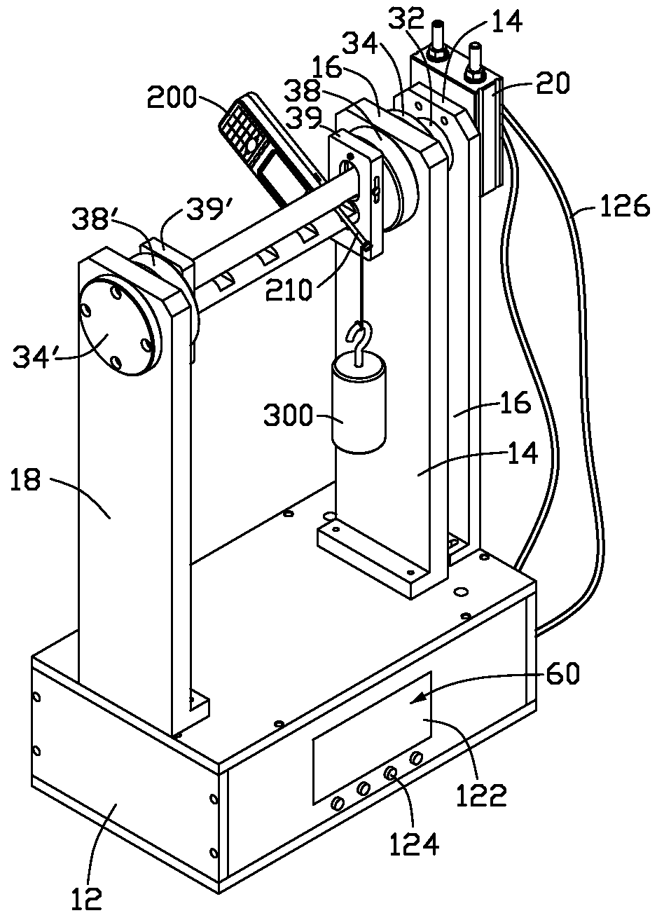
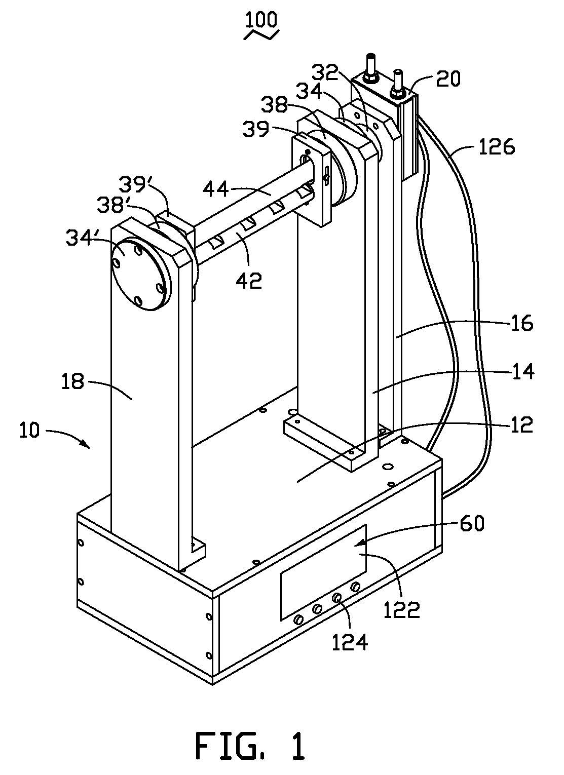
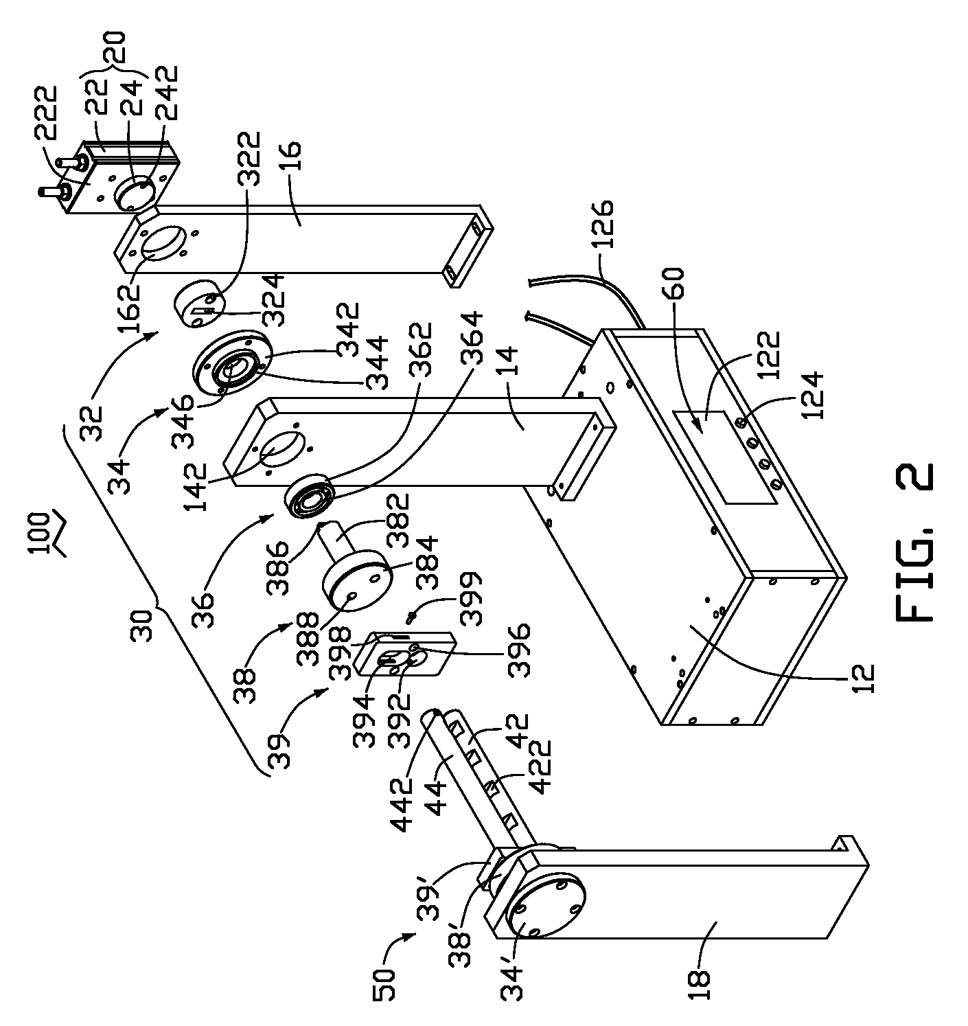
[0010]Referring to FIGS. 1-2, a fatigue test apparatus 100 in accordance with an exemplary embodiment includes a supporting module 10, a driving mechanism 20, a first connecting module 30, a first holding post 42, a second holding post 44, a second connecting module 50, a computer system 60.

[0011]The supporting module 10 includes a base 12, a first supporting arm 14, a second supporting arm 16, and a third supporting arm 18. The base 12 is box-shaped, and receives the computer system 60 therein. A display 122 and a plurality of buttons 124 are located on a sidewall of the base 12. The display 122 and buttons 124 electronically connect with the computer system 60. The supporting arms 14, 16 and 18 are fixed on a top surface of the base 12 spaced apart from each other. The distance between the third supporting arm 18 and the first supporting arm 14 is longer than that of the first supporting arm 14 and the second supporting arm 16. Each of the first and third supporting arms 14, 18 de...


PUM

PropertyMeasurementUnit
rotation speedaaaaaaaaaa
rotation angleaaaaaaaaaa
weightaaaaaaaaaa

Abstract

A fatigue test apparatus for thin workpiece includes a supporting module, a driving mechanism, a first connecting module, a second connecting module, a first holding post, a second holding post and a computer system. The first and second connecting modules are respectively fixed to two sides of the supporting module. Ends of the first holding post and the second holding post are fixed to the first and second connecting modules. The computer system electronically connects with and controls the driving mechanism. The first holding post and the second holding post are drive to rotate by the driving mechanism.

Description

BACKGROUND[0001]1. Technical Field[0002]The present invention relates to fatigue test apparatus, particularly, to a fatigue test apparatus for thin elements of electronic devices.[0003]2. Description of Related Art[0004]In industrial production of electronic devices, it is often necessary to test fatigue strength of some elements (e.g., antenna, flexible circuit board) of the electronic devices, to ensure the quality of the products. In conventional fatigue test for these elements, a fixing device is generally used to hold an element, and the element undergoes repeated bending by an operator until it breaks. However, in conventional fatigue test, the labor intensity of the operator is heavy. In addition, since the operator is unlikely to apply a same force to the element at every time, the result of the fatigue test may be inaccurate.[0005]Therefore, there is space for improvement within the art.BRIEF DESCRIPTION OF THE DRAWINGS[0006]Many aspects of the fatigue test apparatus can be...

Claims


Application Information

Patent Timeline
Patent Type & Authority Applications(United States)
IPC IPC(8): G01N3/20G01M99/00
CPCG01M99/005G01N3/32G01N2203/028G01N2203/0073G01N2033/0078
Inventor LI, LEICHEN, PINGJIANG, ZHI-QIANGWANG, CHUN-YINGZHAI, XUE-LIANGHUANG, LI-PINGCHENG, ZHISUN, CHANG-FADU, XIAN-CUI
Owner SHENZHEN FUTAIHONG PRECISION IND CO LTD
Why Eureka
Try Eureka